SPRAC03 July 2024 IWR6843
4.2.1 Angular Accuracy Error Margins
Between the angles of -40° and 40° there can be an expected angular accuracy error of around ±1°. At max FOV of around 60° you can expect an error of around 5°. This is a general case and angular accuracy may vary based on several factors such as antenna design, processing algorithm, calibration, and test target reflectivity.
For more details on angular and range accuracy as well as how it was measured, see System Performance Measurement With the mmWave Sensor.
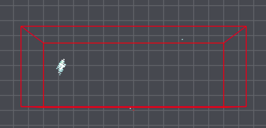
 Figure 4-2 Resulting Point Cloud of a
Detection at 5.5m 65°
Figure 4-2 Resulting Point Cloud of a
Detection at 5.5m 65°As long as the target is not entirely in the first range bin, the accuracy of the range will be based on the chirp configuration’s range resolution. The target being entirely in the first range bin only happens if the detected object is smaller than the chirp configuration’s range resolution, which can go as low as 3 cm.