SPRACM9B June 2019 – November 2020 F29H850TU , TMS320F28384D , TMS320F28384S , TMS320F28386D , TMS320F28386S , TMS320F28388D , TMS320F28388S , TMS320F28P650DH , TMS320F28P650DK , TMS320F28P650SH , TMS320F28P650SK , TMS320F28P659DH-Q1 , TMS320F28P659DK-Q1 , TMS320F28P659SH-Q1
- Trademarks
- 1 Introduction
- 2 Benefits of the TMS320F2838x MCU for High-Bandwidth Current Loop
- 3 Current Loops in Servo Drives
- 4 Outline of the Fast Current Loop Library
- 5 Fast Current Loop Evaluation
- 6 Incremental Build Level 1
- 7 Incremental Build Level 2
- 8 Incremental Build Level 3
- 9 Incremental Build Level 4
- 10Incremental Build Level 5
- 11Incremental Build Level 6
- 12Incremental Build Level 7
- 13Incremental Build Level 8
- 14References
- 15Revision History
7.6.2 Verification of Position Encoder Orientation
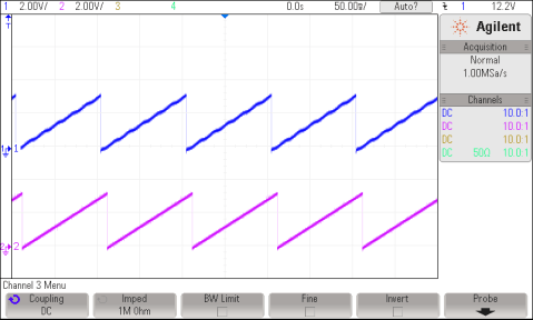
Measured or estimated position information is made available on DAC-C, while the reference position (rg1.Out) used to perform open-loop motor control is displayed on DAC-B. Figure 7-3 shows these signals brought out on H10 on the IDDK, and their scope plots.
 Figure 7-3 Scope Plot of Reference Angle
and Rotor Position
Figure 7-3 Scope Plot of Reference Angle
and Rotor PositionThe waveform of channel 2 represents the reference position, while channel 1 represents the estimated position. The ripple in position estimate is indicative of the fact that the motor runs with some minor speed oscillation. Because of open-loop control, the rotor position and reference position may not align. However, it is important to ensure that the sense of change of the estimated angle is the same as that of the reference; otherwise, it indicates that the motor has a reverse sense of rotation. This can be fixed by either swapping any two wires connecting to the motor, or reversing the angle estimate as in the pseudo code in the software (see Equation 1).
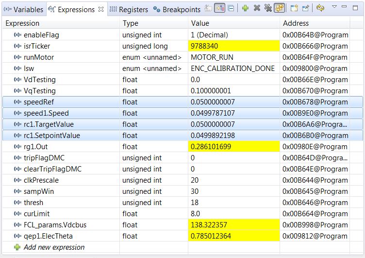
To ensure that the speed estimation is correct, change the speedRef variable in the Expressions window, as shown in Figure 7-4, and check whether the estimated speed variable, speedWe, follows the commanded speed. Because the motor is a PM motor, where there is no slip, the running speed follows the commanded speed regardless of the control being open loop.
 Figure 7-4 Expressions Window
When the tests are complete, bring the system to a safe stop by reducing the bus voltage, taking the controller out of real-time mode, and resetting it. Now, the motor stops.