SPRACN0F October 2021 – March 2023 TMS320F280021 , TMS320F280021-Q1 , TMS320F280023 , TMS320F280023-Q1 , TMS320F280023C , TMS320F280025 , TMS320F280025-Q1 , TMS320F280025C , TMS320F280025C-Q1 , TMS320F280033 , TMS320F280034 , TMS320F280034-Q1 , TMS320F280036-Q1 , TMS320F280036C-Q1 , TMS320F280037 , TMS320F280037-Q1 , TMS320F280037C , TMS320F280037C-Q1 , TMS320F280038-Q1 , TMS320F280038C-Q1 , TMS320F280039 , TMS320F280039-Q1 , TMS320F280039C , TMS320F280039C-Q1 , TMS320F280040-Q1 , TMS320F280040C-Q1 , TMS320F280041 , TMS320F280041-Q1 , TMS320F280041C , TMS320F280041C-Q1 , TMS320F280045 , TMS320F280048-Q1 , TMS320F280048C-Q1 , TMS320F280049 , TMS320F280049-Q1 , TMS320F280049C , TMS320F280049C-Q1 , TMS320F28374D , TMS320F28374S , TMS320F28375D , TMS320F28375S , TMS320F28375S-Q1 , TMS320F28376D , TMS320F28376S , TMS320F28377S , TMS320F28377S-Q1 , TMS320F28378D , TMS320F28378S , TMS320F28379D , TMS320F28379D-Q1 , TMS320F28379S , TMS320F28384D , TMS320F28384S , TMS320F28386D , TMS320F28386S , TMS320F28388D , TMS320F28388S , TMS320F28P650DH , TMS320F28P650DK , TMS320F28P650SH , TMS320F28P650SK , TMS320F28P659DH-Q1 , TMS320F28P659DK-Q1 , TMS320F28P659SH-Q1
- The Essential Guide for Developing With C2000™ Real-Time Microcontrollers
- Trademarks
- 1C2000 and Real-Time Control
-
2Sensing Key Technologies
- 2.1 Accurate Digital Domain Representation of Analog Signals
- 2.2 Optimizing Acquisition Time vs Circuit Complexity for Analog Inputs
- 2.3 Hardware Based Monitoring of Dual-Thresholds Using a Single Pin Reference
- 2.4 Resolving Tolerance and Aging Effects During ADC Sampling
- 2.5 Realizing Rotary Sensing Solutions Using C2000 Configurable Logic Block
- 2.6 Smart Sensing Across An Isolation Boundary
- 2.7 Enabling Intra-Period Updates in High Bandwidth Control Topologies
- 2.8 Accurate Monitoring of Real-Time Control System Events Without the Need for Signal Conditioning
-
3Processing Key Technologies
- 3.1 Accelerated Trigonometric Math Functions
- 3.2 Fast Onboard Integer Division
- 3.3 Hardware Support for Double-Precision Floating-Point Operations
- 3.4 Increasing Control Loop Bandwidth With An Independent Processing Unit
- 3.5 Flexible System Interconnect: C2000 X-Bar
- 3.6 Improving Control Performance With Nonlinear PID Control
- 3.7 Understanding Flash Memory Performance In Real-Time Control Applications
- 3.8 Deterministic Program Execution With the C28x DSP Core
- 3.9 Efficient Live Firmware Updates (LFU) and Firmware Over-The-Air (FOTA) updates
-
4Control Key Technologies
- 4.1 Reducing Limit Cycling in Control Systems With C2000 HRPWMs
- 4.2 Shoot Through Prevention for Current Control Topologies With Configurable Deadband
- 4.3 On-Chip Hardware Customization Using the C2000 Configurable Logic Block
- 4.4 Fast Detection of Over and Under Currents and Voltages
- 4.5 Improving System Power Density With High Resolution Phase Control
- 4.6 Safe and Optimized PWM Updates in High-Frequency, Multi-Phase and Variable Frequency Topologies
- 4.7 Solving Event Synchronization Across Multiple Controllers in Decentralized Control Systems
- 5Interface Key Technologies
- 6Safety Key Technologies
- 7References
- 8Revision History
3.9.2 In Depth
Terminology:
It is important to understand the terminology since there is no single standard that defines this, at least for LFU. The following definitions are used:
- Installation – transfer of the
firmware application or “image” from a host controller to the target (on which
the firmware will execute).
This also includes programming the new firmware on the Flash memory of the target device.
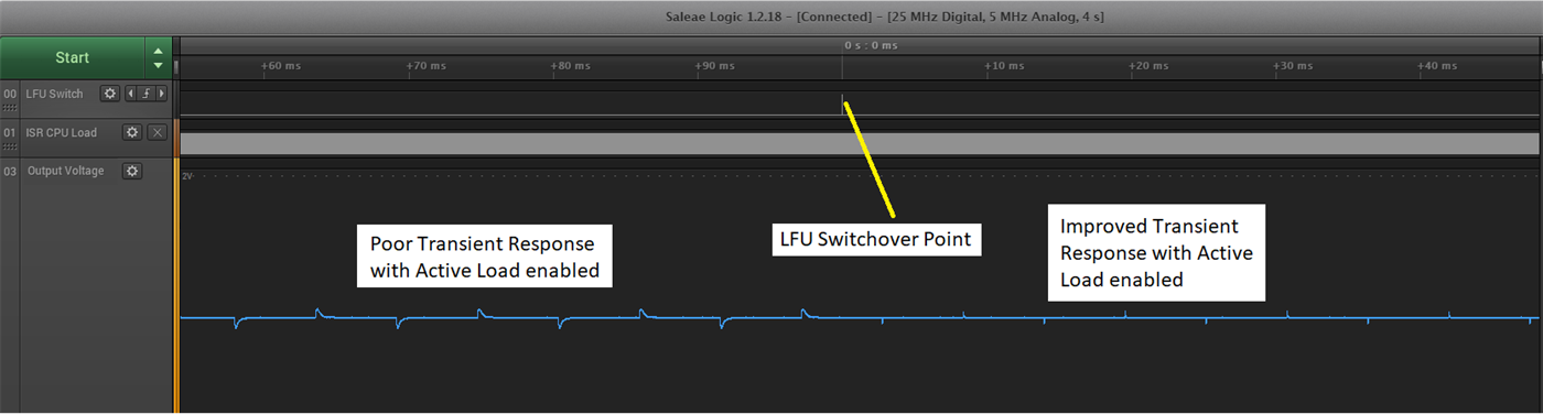
- Activation – as the name suggests, activating the new firmware application. In some of the LFU documentation, the term "Switchover" is also used
- LFU – installation and activation of new firmware occurs without a device reset
- FOTA – installation of new firmware occurs while the old firmware is running, but activation of new firmware requires a device reset
- Swapping – ability to map more than one physical hardware blocks to the same address space. Hardware could refer to flash banks, RAM blocks, interrupt vector tables, and so forth.
Building blocks:
A number of Software and Hardware pieces are available to enable system level features like LFU and FOTA:
- Multiple flash banks – for example, one flash bank containing the active firmware, and the others containing inactive firmware.
- Hardware features to enable LFU – for example, interrupt vector table swapping and RAM block swapping, which enable fast activation for LFU.
- Compiler – an LFU aware compiler, which makes it easier for the user to integrate LFU support into their solution. For LFU, the compiler uses the existing firmware executable as a reference to generate the new firmware executable, which allows activation to be fast and efficient by optimizing the LFU initialization routine.
- Flash kernels – these refer to bootloaders that are provided as examples, reside in Flash, and support LFU and FOTA functionality. They can interact with a host to install firmware, and contain bank selection logic to determine, after a device reset, whether a flash bank contains valid firmware, and which firmware needs to be executed. Bank selection logic is also now built into the Boot ROM of a C2000 MCU and available as a boot mode.
- LFU software examples – simple examples as well as a reference design and a detailed user guide that walks through all the building blocks and LFU flow, enabling them to quickly integrate LFU into their system and achieve optimal performance. This is illustrated with examples of LFU on both the C28x CPU as well as the CLA. With a few changes, these examples can be repurposed for FOTA as well.
There are two flows defined for a LFU:
- At production:
- Program Flash kernel, firmware in one or more flash banks
- In the field:
- Option 1 - with this
approach, you need to know which flash bank the firmware update is
targeted for:
- Developer creates new image (using previous image as reference image and Compiler with LFU support) knowing which flash bank it is targeted to
- Host initiates LFU – downloads image corresponding to inactive bank
- Flash kernel installs image to inactive bank
- Old App (with LFU software/hardware support) activates new App without device reset (if previous step was successful)
- Presence of old App allows fallback option in case of failure
- Option 2 – with this
approach, you do not need to know which Flash bank the firmware
update is targeted for:
- Developer creates two new images (using previous image as reference image and Compiler with LFU support) without knowing which flash bank it is targeted to. For example, if 2 Flash banks are used, and the new version is vN, the user would create vN built for Bank 1 using as reference vN-1 built for Bank 0. The user would also create vN built for Bank 0 using as reference vN-1 built for Bank 1.
- Host initiates LFU – transfers both images to the target device
- Flash kernel installs only the image targeted to the inactive bank, ignores the image targeted to the active bank
- Old App (with LFU software/hardware support) activates new App without device reset (if previous step was successful)
- Presence of old App allows fallback option in case of failure
- Option 1 - with this
approach, you need to know which flash bank the firmware update is
targeted for:
There are two flows applicable to FOTA as well:
- At production:
- Program Flash kernel, firmware in one or more flash banks
- In the field:
- Without hardware support for Flash bank swapping, the factory would need to know which Flash Bank (Bank1 or Bank0) to build the firmware for. This approach is not acceptable because with automotive FOTA, you may freely update from any version to any other version, that is, skip versions, so it is impossible to pose a constraint like this
- So a viable approach would be to always build the firmware to be Loaded to Bank1, and Run from Bank0. Since swapping is not available, the activation process involves copying the image from Bank1 to Bank0. The problem here is once the firmware is copied from Bank1 to Bank0, both Banks have the same new firmware now, without a valid backup present in case a rollback is needed. Since a rollback is an essential requirement with FOTA, a 3rd partition, or Flash bank, is needed
- Developer creates new firmware to be loaded to Bank 1 and run from Bank 0
- Host (FOTA Master ECU) initiates FOTA – transfers image to target device
- Flash kernel installs image to Bank 1
- Host initiates device reset. The old image in Bank 0 is copied by the Flash kernel to Bank 2 to be available in case a rollback is needed. Then the new image in Bank 1 is copied by the Flash kernel to Bank 0. Then the regular image activation steps occur
- Constraints:
- FOTA without Flash bank swapping requires three Flash banks or partitions
- In general, with LFU, firmware updates cannot be skipped since the reference image is needed for activation to be fast and efficient.
- With FOTA, firmware updates can be skipped since there is no constraint on activation time, and activation occurs after a device reset, so a reference image is not needed