AWR2243 Bootloader Flow
Trademarks
All trademarks are the property of their respective owners.
1 Introduction
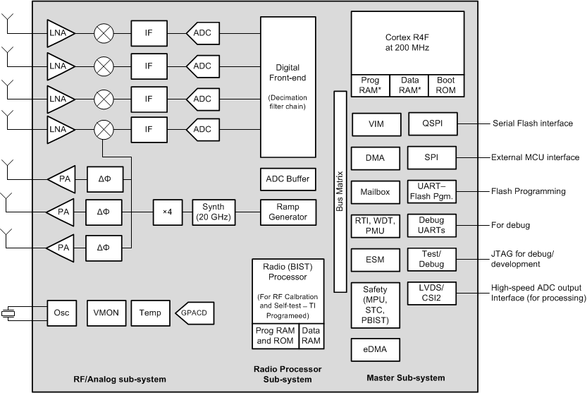
AWR2243 Device could be broadly split as two sub-systems:
- Master Subsystem:
- Bootloader – Responsible for the device initialization, boot time tests, APLL open loop calibration, loading of application images, downloading of images to SFLASH (device management mode, SOP5).
- Functional firmware – Is responsible for the external host API communication, BSS API handshake, data path (LVDS/CSI2) control, safety and monitoring of the entire device.
- Radar/Millimetre Wave Subsystem:
- Is responsible for configuring RF/analog and digital
front-end in real-time, as well as to periodically schedule calibration
and functional safety monitoring. This enables the mm-Wave front-end to
be self-contained and capable of adapting itself to handle temperature
and ageing effects, and to enable significant ease-of-use from an
external host perspective.
 Figure 1-1 Simplified
Representation of AWR2243
Device
- Is responsible for configuring RF/analog and digital
front-end in real-time, as well as to periodically schedule calibration
and functional safety monitoring. This enables the mm-Wave front-end to
be self-contained and capable of adapting itself to handle temperature
and ageing effects, and to enable significant ease-of-use from an
external host perspective.
- Master subsystem is the first programmable block to get activated after AWR2243 device reset is de-asserted. AWR2243 device’s bootloader is hosted in master subsystem’s read only memory (ROM) and takes control immediately.
- From this point onwards, the AWR2243 bootloader can operate in two modes: Flashing and Execution modes.
- Bootloader looks for the state of Sense On Power (SOP) I/Os (SOP
lines – driven externally for choosing the specific mode). Table 1-1 Sense On Power (SOP) Lines and Boot Modes
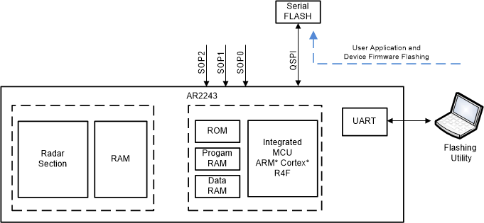
SOP2 SOP1 SOP0 Bootloader mode & operation 0 0 1 Functional Mode Primary deployment mode. After the patches are loaded (over SFLASH or SPI), the functional firmware executes and the device is controlled by commands over SPI. The ADC data is available on the high speed interface of choice (LVDS/CSI2). 1 0 1 Device Management Mode Flash programming mode. The images (patches) are downloaded onto the SFLASH using a flashing utility that transfers the images over the UART. - Device Management (Flashing) Mode of the bootloader allows an
external entity to load the customer application image to SerialDataFlash (SDF).
 Figure 1-2 Flashing Mode of
Bootloader
 - Execution (or Functional) Mode of the
bootloader has two boot modes:
- Boot Mode – SFLASH (Development Phase)
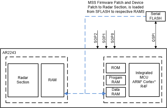
If the presence of a Serial Flash is detected with a valid image, the bootloader relocates the image stored in SDF to R4F and Radar section memory subsystems. Towards the end of this process, bootloader would pass the control MSS Functional firmware.
The SFLASH is present only in development versions of the silicon where the functional firmware (MSS and Radar section) does not execute from ROM, hence, it is a large image size.
 Figure 1-3 Execution Mode
of Bootloader (image load from SFLASH)
 - Boot Mode – SPI (Deployment Phase)
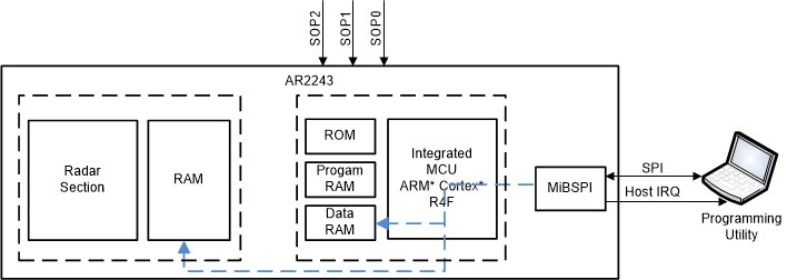
If the serial flash is not detected or a valid image is not detected in the serial flash, the bootloader loads the images (patches) to the respective memories of the MSS R4F and Radar section subsystems by receiving the data from an external host over SPI. Towards the end of this process, the bootloader would pass the control MSS Functional firmware.
 Figure 1-4 Execution Mode
of Bootloader (image load over SPI)
- Boot Mode – SFLASH (Development Phase)
2 Basic Bootloader Flow
A high level bootloader operation could be split into three phases:
- Device Initialization: bootloader uses “Built In Self Test” (BIST) Engines for hardware diagnostics (for example, RAM tests)
- Sets up the root clock by starting the APLL
- Checks SOP lines to proceed with either the Flashing or Execution Modes
 Figure 2-1 Basic Bootloader Flow Chart