SPRAD34B July 2023 – October 2023 MSPM0G1507
- 1
- Abstract
- Trademarks
- 1Introduction
- 2Getting Started With MSPM0 Motor Control
- 3Brushed-DC Motor Control
- 4Stepper Motor Control
- 5BLDC Sensored Trap Control
- 63-Phase Sensorless FOC Control
- 7References
- Revision History
4.1 Background
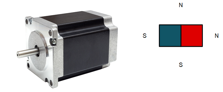
Stepper motors are prevalent because they allow for fine position control without requiring external sensors or complex control algorithms. This is known as open loop position control, which can be used to allow the stepper motor to provide continuous motion of maintain a fixed rotor position depending on the system requirements. These features make steppers easy to implement and a low-cost design for system designers.

Stepper motors are commutated by energizing two phases, which requires two full H bridges to provide current direction and magnitude for each of the phase currents. This is used to move the rotor in a stepper motor with position and torque control, depending on the application. Bipolar stepper motors also have a specified resolution in degrees per full step to indicate how many mechanical degrees a stepper will commutate when a full electrical period is applied on each phase.
Typically, full-stepping refers to a full electrical period using four indexes to energize the two windings in all four current directions to commutate the stepper the specified mechanical period. To provide more precise position and torque control, non-circular or circular half-stepping provides more resolution and current regulation to smoothen the electrical commutation pattern by using eight indexes to energize the two windings. Both full-stepping and circular half-stepping current waveforms are shown in Figure 4-1. These methods of full stepping, non-circular half-stepping, and circular half-stepping are simple to implement using a microcontroller’s GPIO or PWM pins and a simple stepper driver with a PWM interface.

 Figure 4-1 Full and Circular-Half
Stepping in Stepper Motor Control
Figure 4-1 Full and Circular-Half
Stepping in Stepper Motor ControlSmaller step sizes can be implemented by factors of half (1/4, 1/8, 1/16, 1/32, etc.) down to 1/256 to create a sinusoidal current drive and reduce the noise and torque implemented in the stepper motor. Using step sizes less than 1/4 is generally referred to as microstepping because an indexer and current regulation is used to implement discrete intervals for precise position and torque control. An example of using 1/16 microstepping is shown in Figure 4-2. Microstepping is more difficult to implement in software, so using an intelligent stepper motor driver and a simple MCU with one PWM and analog integration is optimal for low-noise, high-precision stepper drives.
 Figure 4-2 Microstepping in Stepper Motor
Control