SPRADC5 January 2024
2.1 Steps to Configure the PinMux
- Go to https://dev.ti.com/sysconfig/?fromPinmux=true#/start.
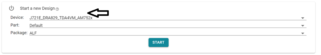
- In the “Start a new Design” Pick
an existing design that matches your part number. For example,
J721E_DRA829_TDA4VM_AM752x.
Keep the “Part” tab default and “Package” ALF. Click “Start” button as shown in the screenshot below:
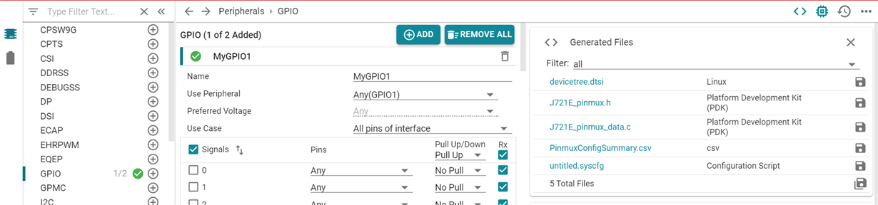
- Choose the peripheral by entering
the corresponding name in the “Type Filter Text” (left top of the page). For
example, GPIO and Click “+” sign. This adds a module on the center.
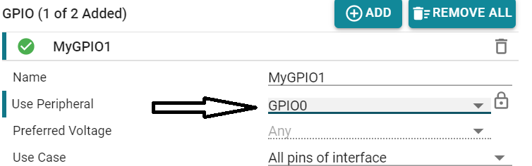
- MyGPIO1 has some defaults. Choose
the exact module instance in the “Use peripheral” menu.By default it will be
ANY. Select the appropriate instance using the drop down menu. For this case,
GPIO0 is used.
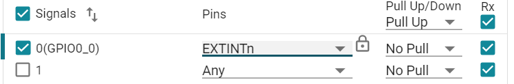
- With
this, we are done with module level selection. Now we just need to pick the ball
name that maps to the one present in the board schematics. This can be
accomplished by choosing the right ball name in the “Pins” drop down menu. Based
on schematics pick appropriate “Pull Up/Down” from the drop down menu. For
information on how to pick the pin name EXTINTn, see the Manual audit of the
pinmux details below.
- From the “Generated Files”
section, based on the choice of OS, download one of these files: - Linux:
devicetree.dtsi: Just need to copy paste the node as is under the right parent
pinmux node (see below for details) - PDK(RTOS): J721E_pinmux.h/
J721E_pinmux.c.

- For example, Linux:
devicetree.dtsi.
main gpio0 was chosen, hence, the pinmux node for the example mygpio1_pins_default should come under main_pmx0 node in arch/arm64/boot/dts/ti/j721-common-proc-board.dts file.
&main_pmx0 { pinctrl-single,pins = < J721E_IOPAD(0x0, PIN_INPUT, 7) /* (AC18) EXTINTn.GPIO0_0 */ >; }; }; - For example, Linux:
devicetree.dtsi.
The same can be followed with u-boot device tree. The very same example arch/arm/dts/j721-common-proc-board.dts file.