SPRADG4A January   2024  – April 2024


  1.   1
  2.   Abstract
  3.   Trademarks
  4. 1General Texas Instruments High Voltage Evaluation (TI HV EVM) User Safety Guidelines
  5. 2Introduction
  6. 3System Description
    1. 3.1 Key System Specifications
  7. 4System Overview
    1. 4.1 Block Diagram
    2. 4.2 Basic Operation
    3. 4.3 System Design Theory
      1. 4.3.1 Peak Current Mode Control (PCMC) Implementation
      2. 4.3.2 Zero Voltage Switching (ZVS) or Low Voltage Switching (LVS)
      3. 4.3.3 Synchronous Rectification
      4. 4.3.4 Slope Compensation
  8. 5Hardware
    1. 5.1 Hardware Overview
    2. 5.2 Hardware and Test Instruments Required
    3. 5.3 TMDSCNCD263 controlCARD™ Changes
  9. 6Software
    1. 6.1 Getting Started With Firmware
      1. 6.1.1 Opening the Code Composer Studio Project
      2. 6.1.2 Software Architecture
      3. 6.1.3 Project Folder Structure
    2. 6.2 SysConfig Setup
      1. 6.2.1 EPWM Configuration
      2. 6.2.2 ADC Configuration
      3. 6.2.3 CMPSS Configuration
    3. 6.3 Incremental Builds
      1. 6.3.1 Procedure for Running the Incremental Builds - PCMC
        1. 6.3.1.1 Lab 1: Phase Overlapping Check With Open Current and Voltage Loop
          1. 6.3.1.1.1 Objective of Lab 1
          2. 6.3.1.1.2 Overview of Lab 1
          3. 6.3.1.1.3 Procedure of Lab 1
            1. 6.3.1.1.3.1 Start CCS and Open a Project for Lab 1
            2. 6.3.1.1.3.2 Build and Load the Project for Lab 1
            3. 6.3.1.1.3.3 Debug Environment Windows for Lab 1
            4. 6.3.1.1.3.4 Run the Code for Lab 1
        2. 6.3.1.2 Lab 2: Closed Current and Open Voltage Loop
          1. 6.3.1.2.1 Objective of Lab 2
          2. 6.3.1.2.2 Overview of Lab 2
          3. 6.3.1.2.3 Procedure of Lab 2
            1. 6.3.1.2.3.1 Build and Load Project for Lab 2
            2. 6.3.1.2.3.2 Debug Environment Windows for Lab 2
            3. 6.3.1.2.3.3 Run the Code for Lab 2
        3. 6.3.1.3 Lab 3: Closed Current and Closed Voltage Loop
          1. 6.3.1.3.1 Objective of Lab 3
          2. 6.3.1.3.2 Overview of Lab 3
          3. 6.3.1.3.3 Procedure of Lab 3
            1. 6.3.1.3.3.1 Build and Load Project for Lab 3
            2. 6.3.1.3.3.2 Debug Environment Windows for Lab 3
            3. 6.3.1.3.3.3 Run the Code for Lab 3
  10. 7Testing and Results
    1. 7.1 Lab 0: Basic PWM Check
    2. 7.2 Lab 1: Phase Overlapping Check With Open Current and Voltage Loop
    3. 7.3 Lab 2: Closed Current and Open Voltage Loop
    4. 7.4 Lab 3: Closed Current and Closed Voltage Loop
  11. 8References
  12. 9Revision History
Build and Load the Project for Lab 1
  1. Click on the expand sign (>) on the left of the project name PCMC_PSFB_am263x-cc_r5fss0-0_nortos_ti-arm-clang and open the psfbpcmc_settings.h as shown in Lab 1 setup. The setting is #define INCR_BUILD 1. This enables the build 1 solution.
  2. Set #define PSFB_PCMC 0 in the psfbpcmc_settings.h. The default value of PSFB_PCMC is defined as 1 to execute closed current loop (this mode is discussed in detail in upcoming sections).
  3. Click on the View tab on the top left. Click on Target Configuration. The Target Configuration window opens. Right click on user defined and select Import Target Configuration. Browse to the CCS workspace where the project was imported. Open the targetConfigs folder and select the AM263x_Real_Time_debug.ccxml.
  4. Double click on AM263x_Real_Time_debug.ccxml and do the Test Connection check. If the check fails, change the COM Port number following the steps mentioned in AM263x Real Time Debug setup. This COM Port number varies from one controlCARD to another. Proceed further only when Test Connection is successfully passed.
  5. Turn ON the 5V DC bench power supply. Connect the USB cable to the Control card and make sure LD7 is glowing green. In the Target Configuration window, select AM263x_Real_Time_debug.ccxml. Click on the Debug button. The Lab 1 code is built successfully without any error.
  6. Notice the CCS Debug icon in the upper right corner indicating that the process is now in the Debug Perspective view. Right click on the Cortex_R5_0 in the Debug window and select Connect Target. Now click on the Load icon from the tab on the top side. Load the .out file which was just built successfully. Now .out is successfully loaded to Core_0. The program is stopped at the start of main().
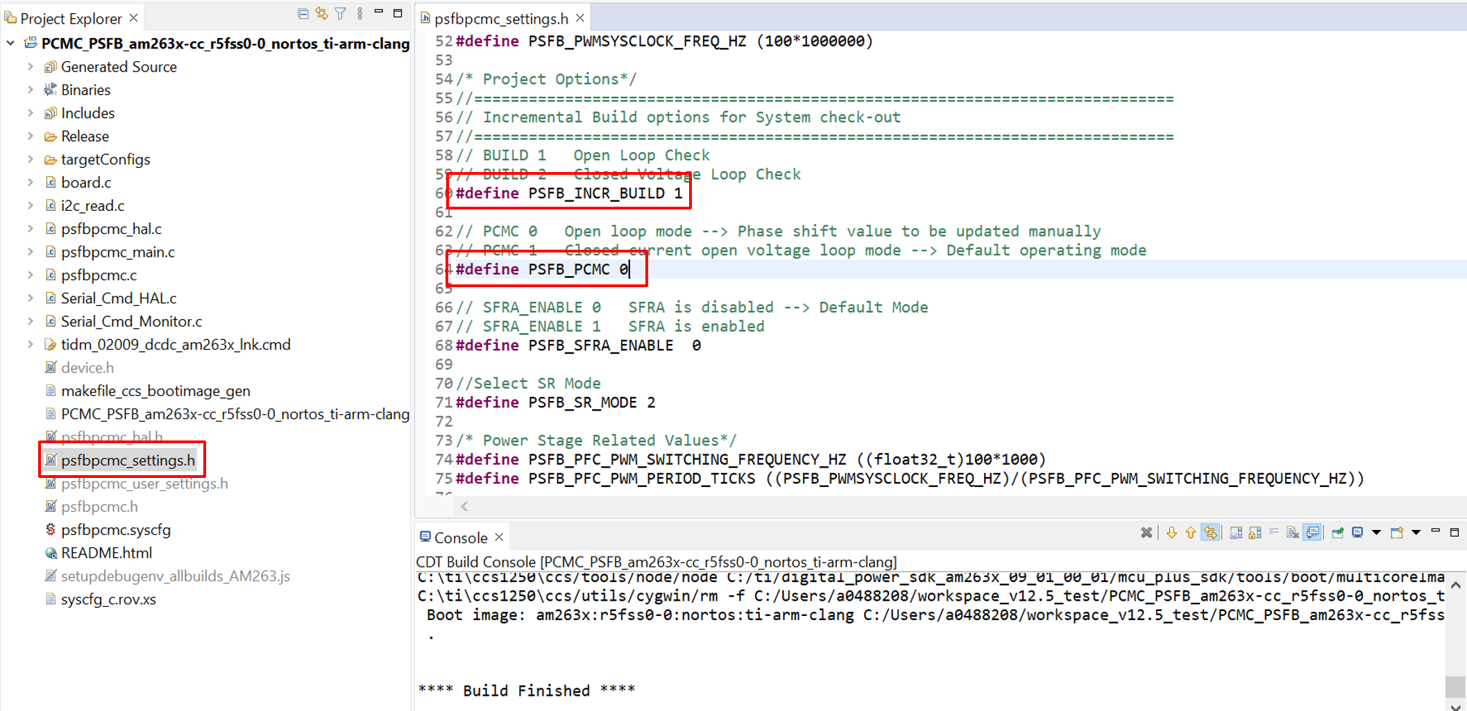
GUID-8D455E7F-CABE-4D16-9CE2-23256B7C359E-low.pngFigure 6-6 Lab 1 Setup