SPRADH3 September 2024 UCC5880-Q1
2.1 Gate drivers
Earlier generations of the gate drivers used in HEV/EV were much simpler. Systems safety requirements have become more complex and additional features have been implemented to achieve higher efficiency. Although these features can be implemented discretely, having them inside the package saves a lot of the space on the board and reduces the system cost. Active short circuit (ASC), DESAT, soft turn-off, Miller clamp and on-fly programmable drive strengths are just some of the features that are implemented in the UCC5880-Q1 isolated gate driver.
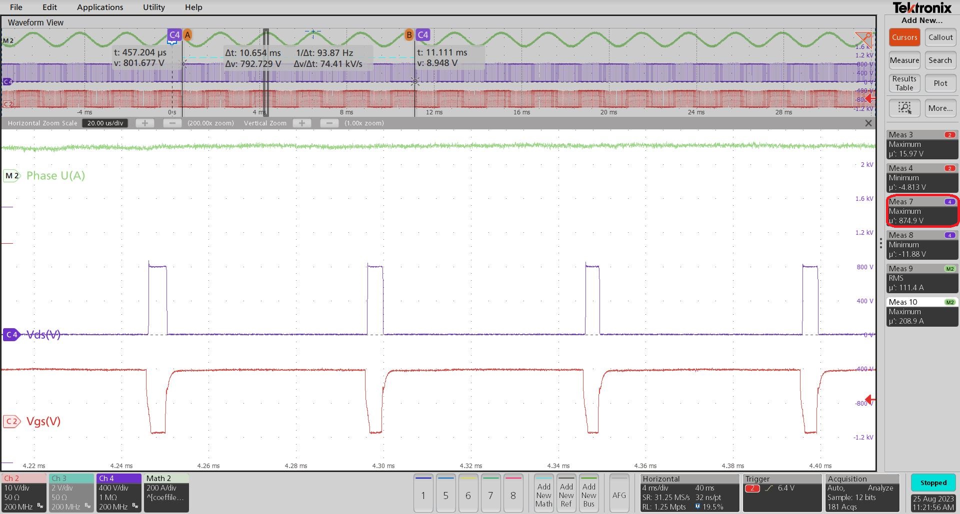
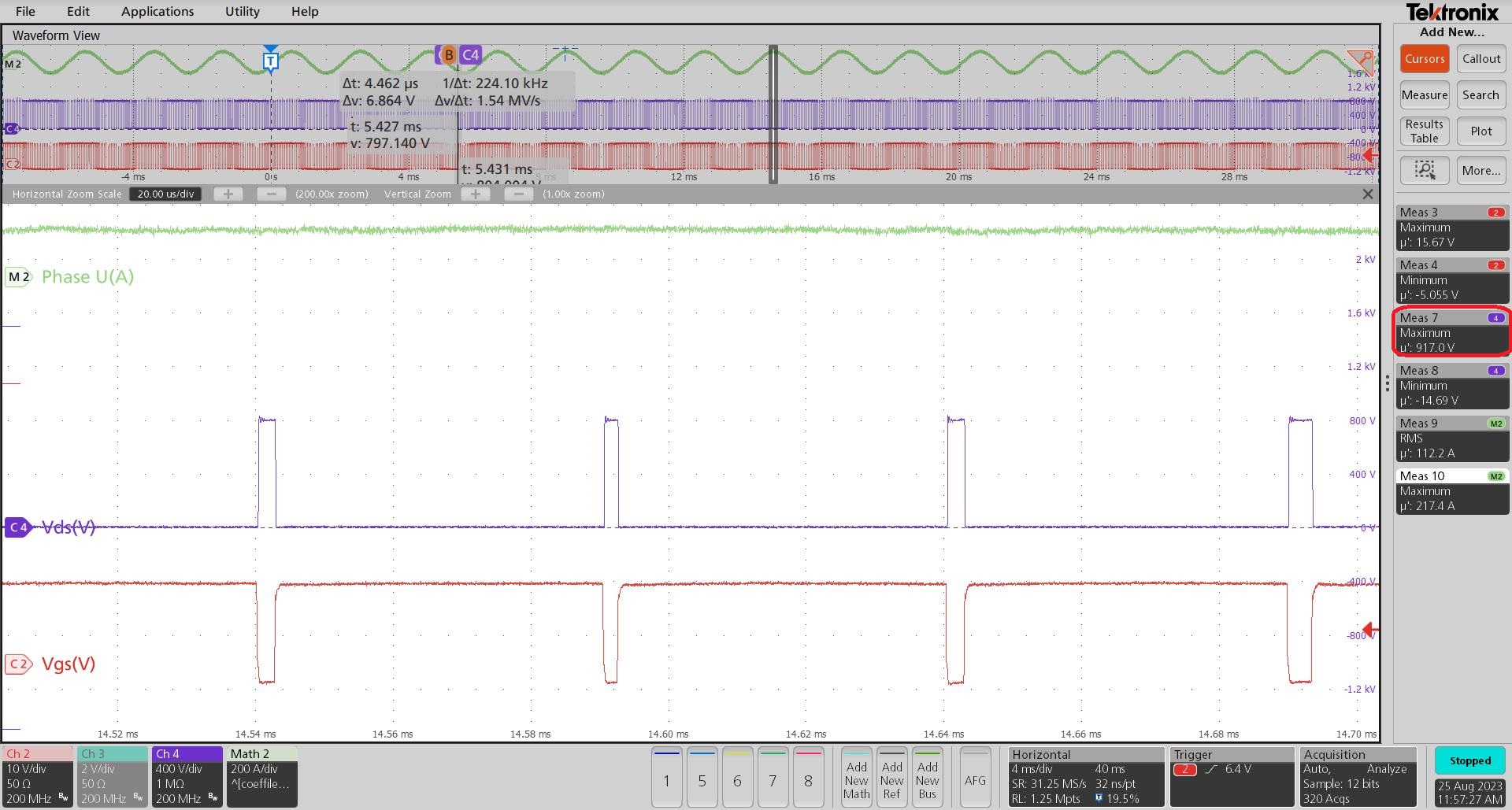
Adjustable drive strength has a significant effect on the efficiency improvement. Having the possibility to drive a power switch with higher current minimizes the turn-on and turn-off time and therefore the switching losses. Although this strong drive increases the inverter efficiency, this must not be used all the time. Fast switching brings the benefits at the light load conditions and when battery voltage is lower, while the slow switching is mainly used for heavy loads. Each power module is rated for the specific maximum voltage (for example EAB450M12XM3 is rated for 1200V). Due to the stray inductance, stronger switching leads to the higher voltage overshoot and therefore close to the voltage limit of the module. If gate driver continues switching this way, it brings the stress on the power module and therefore decreasing the lifetime. Another benefit of having the adjustable gate drive strengths is the EMI improvement. Changing the dv/dt improves the EMI after the 2nd corner frequency. Figure 2-1 and Figure 2-2 show the high-power test results taken at 800V DC-Link voltage, 7000rpm and 150Nm, for the weak and strong drive respectively. These waveforms are showing the difference in the Vgs falling and rising edges as well as the Vds overshoot when driving with two different gate strengths. Channels descriptions are as following:
- M2 (Phase U(A)): Phase current, 200A/div
- Ch2 (Vgs): Gate-source voltage, 10V/div
- Ch4 (Vds): Drain-source voltage, 400V/div
 Figure 2-1 Switching Waveforms at 800V,
7000rpm, 150Nm and Weak Drive
 Figure 2-2 Switching Waveforms at 800V,
7000rpm, 150Nm and Strong Drive
Figure 2-2 Switching Waveforms at 800V,
7000rpm, 150Nm and Strong DriveFrom the oscilloscope is visible that the maximum voltage overshoot for the weak drive and this specific operation point was 75V, while the strong drive was 117V.