SPRADI0 July 2024
2.3.3 Test Procedure
To run the algorithm on hardware, configure the hardware parameters corresponding to inverter and motor by selecting Edit motor & inverter parameters option in the TIDM_02012_F280039C_MBD example. This opens up the tidm_2012_param_init_script.m that contains the motor and inverter parameter initializations such as the PWM frequency, data type, motor model number and electrical parameters. It also contains C2000 device initialization parameters such as device part number, frequency, PWM, ADC configuration.
User is expected to update the parameter based on the application.
Before running the algorithm on hardware, the control loop algorithm can be tested using simulation in Simulink. To run the simulation, once all the parameters for the motor and inverter are configured, click on Simulation’ tab in the Simulink window and click on ‘Run. The execution of simulation can be checked by putting scope or data display blocks wherever desired in the example. By opening the Simulink Data Inspector from the Apps tab in Simulink, the preset parameters are available to watch. You are free to add more parameters that might be needed for validation of the algorithm.
Keep in mind, that while running the simulation, no code is being generated. It is just the control algorithm that can be validated for operation. The C2000 device F280039C is not needed to be connected until this point.
Once the simulation is validated, to deploy the code on the hardware, select the Hardware tab and choose Build, Deploy and Start as shown in Figure 2-5. Ensure that the hardware is already connected for the code to be deployed. The code starts running as soon as it is deployed on the hardware.
 Figure 2-5 Build, Deploy and
Start
Figure 2-5 Build, Deploy and
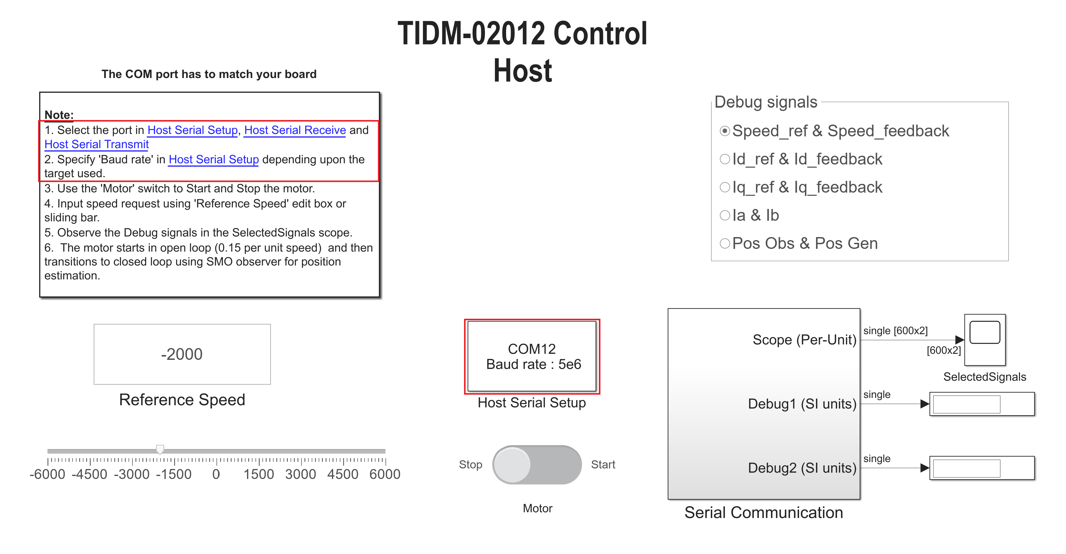
StartTo control the motor operation such as start-stop, motor speed and watch the run time parameters such as speed, current, etc., a separate example file TIDM_02012_control_host model has to be used. Open the file and choose the correct COM port for UART communication. Ensure the same COM port is enabled in Host Serial Setup, Host Serial Receive and Host Serial Transmit as highlighted in Figure 2-6.
 Figure 2-6 Host Serial
Configuration
Figure 2-6 Host Serial
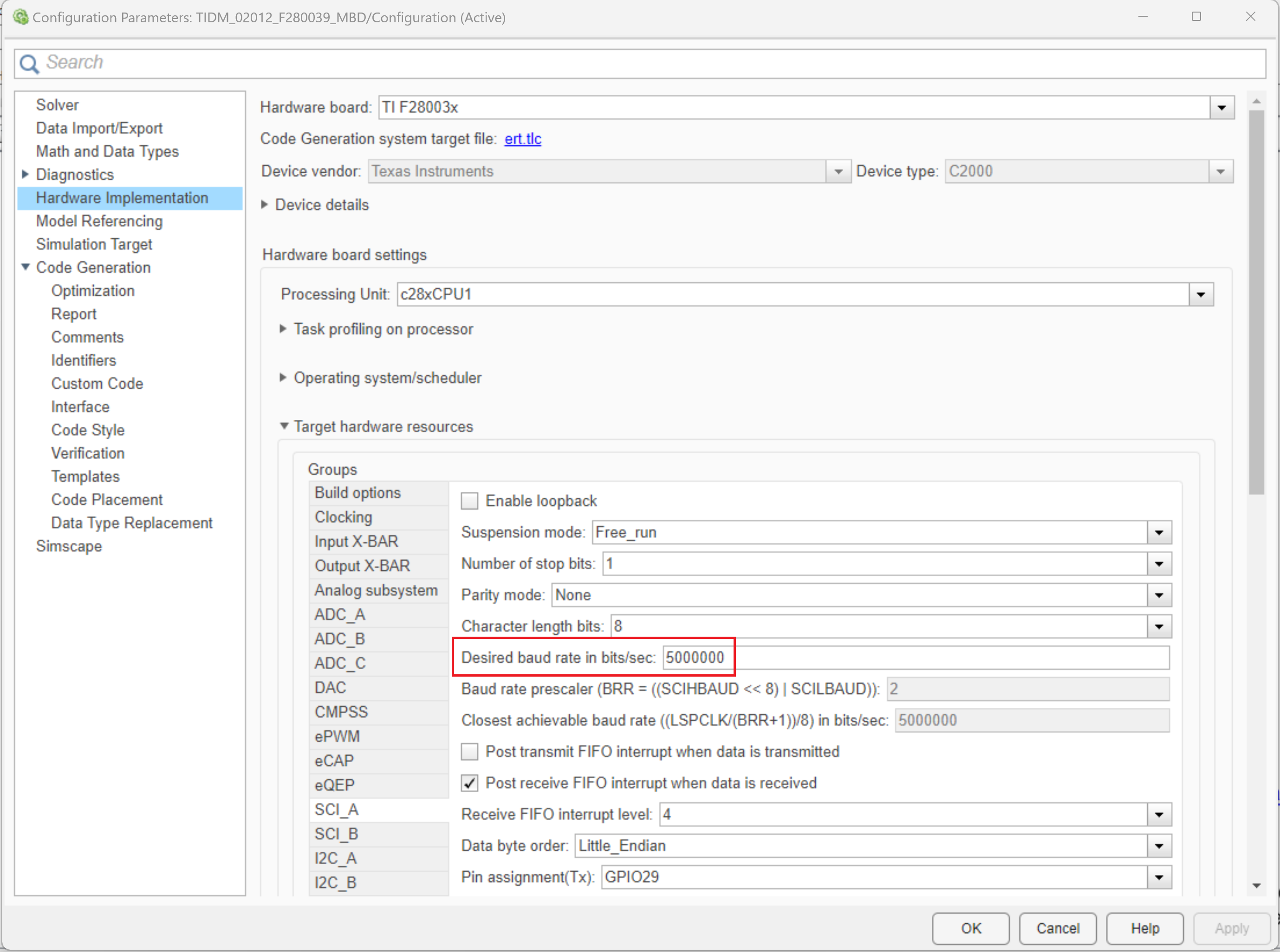
ConfigurationThe baud rate for communication with the device is to be configured the same as what is configured in control algorithm model that was deployed on the hardware, the default value on the example is 5e6. To check in the main example, open model explorer (Ctrl + E), go to Hardware Implementation, expand the drop down Target hardware resources and check the configured baud rate under SCIA as shown in Figure 2-7.
 Figure 2-7 Baud Rate
Configuration
Figure 2-7 Baud Rate
ConfigurationRun the control host example by clicking on Run in the simulation tab. Keep the simulation time as ‘Inf’ for continuous execution. The selected parameter from the options will now be continuously read and plotted on the scope when the motor is started. Additionally, the motor speed can also be controlled by moving the marker or by providing input in the box.