SPRS717L October 2011 – March 2020 AM3351 , AM3352 , AM3354 , AM3356 , AM3357 , AM3358 , AM3359
PRODUCTION DATA.
- 1Device Overview
- 2Revision History
- 3Device Comparison
- 4Terminal Configuration and Functions
-
5Specifications
- 5.1 Absolute Maximum Ratings
- 5.2 ESD Ratings
- 5.3 Power-On Hours (POH)
- 5.4 Operating Performance Points (OPPs)
- 5.5 Recommended Operating Conditions
- 5.6 Power Consumption Summary
- 5.7 DC Electrical Characteristics
- 5.8 Thermal Resistance Characteristics for ZCE and ZCZ Packages
- 5.9 External Capacitors
- 5.10 Touch Screen Controller and Analog-to-Digital Subsystem Electrical Parameters
-
6Power and Clocking
- 6.1 Power Supplies
- 6.2
Clock Specifications
- 6.2.1 Input Clock Specifications
- 6.2.2 Input Clock Requirements
- 6.2.3 Output Clock Specifications
- 6.2.4 Output Clock Characteristics
-
7Peripheral Information and Timings
- 7.1 Parameter Information
- 7.2 Recommended Clock and Control Signal Transition Behavior
- 7.3 OPP50 Support
- 7.4 Controller Area Network (CAN)
- 7.5 DMTimer
- 7.6
Ethernet Media Access Controller (EMAC) and Switch
- 7.6.1
EMAC and Switch Electrical Data and Timing
- Table 7-7 EMAC and Switch Timing Conditions
- 7.6.1.1 EMAC/Switch MDIO Electrical Data and Timing
- 7.6.1.2
EMAC and Switch MII Electrical Data and Timing
- Table 7-11 Timing Requirements for GMII[x]_RXCLK - MII Mode
- Table 7-12 Timing Requirements for GMII[x]_TXCLK - MII Mode
- Table 7-13 Timing Requirements for GMII[x]_RXD[3:0], GMII[x]_RXDV, and GMII[x]_RXER - MII Mode
- Table 7-14 Switching Characteristics for GMII[x]_TXD[3:0], and GMII[x]_TXEN - MII Mode
- 7.6.1.3 EMAC and Switch RMII Electrical Data and Timing
- 7.6.1.4
EMAC and Switch RGMII Electrical Data and Timing
- Table 7-18 Timing Requirements for RGMII[x]_RCLK - RGMII Mode
- Table 7-19 Timing Requirements for RGMII[x]_RD[3:0], and RGMII[x]_RCTL - RGMII Mode
- Table 7-20 Switching Characteristics for RGMII[x]_TCLK - RGMII Mode
- Table 7-21 Switching Characteristics for RGMII[x]_TD[3:0], and RGMII[x]_TCTL - RGMII Mode
- 7.6.1
EMAC and Switch Electrical Data and Timing
- 7.7
External Memory Interfaces
- 7.7.1 General-Purpose Memory Controller (GPMC)
- 7.7.2
mDDR(LPDDR), DDR2, DDR3, DDR3L Memory Interface
- 7.7.2.1
mDDR (LPDDR) Routing Guidelines
- 7.7.2.1.1 Board Designs
- 7.7.2.1.2 LPDDR Interface
- 7.7.2.1.3 LPDDR CK and ADDR_CTRL Routing
- 7.7.2.2
DDR2 Routing Guidelines
- 7.7.2.2.1 Board Designs
- 7.7.2.2.2
DDR2 Interface
- 7.7.2.2.2.1 DDR2 Interface Schematic
- 7.7.2.2.2.2 Compatible JEDEC DDR2 Devices
- 7.7.2.2.2.3 PCB Stackup
- 7.7.2.2.2.4 Placement
- 7.7.2.2.2.5 DDR2 Keepout Region
- 7.7.2.2.2.6 Bulk Bypass Capacitors
- 7.7.2.2.2.7 High-Speed (HS) Bypass Capacitors
- 7.7.2.2.2.8 Net Classes
- 7.7.2.2.2.9 DDR2 Signal Termination
- 7.7.2.2.2.10 DDR_VREF Routing
- 7.7.2.2.3 DDR2 CK and ADDR_CTRL Routing
- 7.7.2.3
DDR3 and DDR3L Routing Guidelines
- 7.7.2.3.1 Board Designs
- 7.7.2.3.2 DDR3 Device Combinations
- 7.7.2.3.3
DDR3 Interface
- 7.7.2.3.3.1 DDR3 Interface Schematic
- 7.7.2.3.3.2 Compatible JEDEC DDR3 Devices
- 7.7.2.3.3.3 PCB Stackup
- 7.7.2.3.3.4 Placement
- 7.7.2.3.3.5 DDR3 Keepout Region
- 7.7.2.3.3.6 Bulk Bypass Capacitors
- 7.7.2.3.3.7 High-Speed Bypass Capacitors
- 7.7.2.3.3.8 Net Classes
- 7.7.2.3.3.9 DDR3 Signal Termination
- 7.7.2.3.3.10 DDR_VREF Routing
- 7.7.2.3.3.11 VTT
- 7.7.2.3.4 DDR3 CK and ADDR_CTRL Topologies and Routing Definition
- 7.7.2.3.5 Data Topologies and Routing Definition
- 7.7.2.3.6 Routing Specification
- 7.7.2.1
mDDR (LPDDR) Routing Guidelines
- 7.8 I2C
- 7.9 JTAG Electrical Data and Timing
- 7.10 LCD Controller (LCDC)
- 7.11 Multichannel Audio Serial Port (McASP)
- 7.12 Multichannel Serial Port Interface (McSPI)
- 7.13
Multimedia Card (MMC) Interface
- 7.13.1
MMC Electrical Data and Timing
- Table 7-89 MMC Timing Conditions
- Table 7-90 Timing Requirements for MMC[x]_CMD and MMC[x]_DAT[7:0]
- Table 7-91 Switching Characteristics for MMC[x]_CLK
- Table 7-92 Switching Characteristics for MMC[x]_CMD and MMC[x]_DAT[7:0]—Standard Mode
- Table 7-93 Switching Characteristics for MMC[x]_CMD and MMC[x]_DAT[7:0]—High-Speed Mode
- 7.13.1
MMC Electrical Data and Timing
- 7.14
Programmable Real-Time Unit Subsystem and Industrial Communication Subsystem (PRU-ICSS)
- 7.14.1 Programmable Real-Time Unit (PRU-ICSS PRU)
- 7.14.2
PRU-ICSS EtherCAT (PRU-ICSS ECAT)
- Table 7-100 PRU-ICSS ECAT Timing Conditions
- 7.14.2.1
PRU-ICSS ECAT Electrical Data and Timing
- Table 7-101 PRU-ICSS ECAT Timing Requirements – Input Validated With LATCH_IN
- Table 7-102 PRU-ICSS ECAT Timing Requirements – Input Validated With SYNCx
- Table 7-103 PRU-ICSS ECAT Timing Requirements – Input Validated With Start of Frame (SOF)
- Table 7-104 PRU-ICSS ECAT Timing Requirements - LATCHx_IN
- Table 7-105 PRU-ICSS ECAT Switching Requirements - Digital I/Os
- 7.14.3 PRU-ICSS MII_RT and Switch
- 7.14.4 PRU-ICSS Universal Asynchronous Receiver Transmitter (PRU-ICSS UART)
- 7.15 Universal Asynchronous Receiver Transmitter (UART)
- 8Device and Documentation Support
- 9Mechanical, Packaging, and Orderable Information
Table 7-78 Switching Characteristics for LCD LIDD Mode
(see Figure 7-72 through Figure 7-80)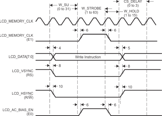
A. Hitachi mode performs asynchronous operations that do not require an external LCD_MEMORY_CLK. The first LCD_MEMORY_CLK waveform is only shown as a reference of the internal clock that sequences the other signals. The second LCD_MEMORY_CLK waveform is shown as E1 because the LCD_MEMORY_CLK signal is used to implement the E1 function in Hitachi mode.
Figure 7-71 Command Write in Hitachi Mode 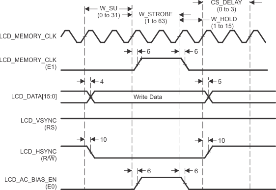
A. Hitachi mode performs asynchronous operations that do not require an external LCD_MEMORY_CLK. The first LCD_MEMORY_CLK waveform is only shown as a reference of the internal clock that sequences the other signals. The second LCD_MEMORY_CLK waveform is shown as E1 because the LCD_MEMORY_CLK signal is used to implement the E1 function in Hitachi mode.
Figure 7-72 Data Write in Hitachi Mode 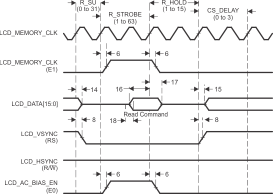
A. Hitachi mode performs asynchronous operations that do not require an external LCD_MEMORY_CLK. The first LCD_MEMORY_CLK waveform is only shown as a reference of the internal clock that sequences the other signals. The second LCD_MEMORY_CLK waveform is shown as E1 because the LCD_MEMORY_CLK signal is used to implement the E1 function in Hitachi mode.
Figure 7-73 Command Read in Hitachi Mode 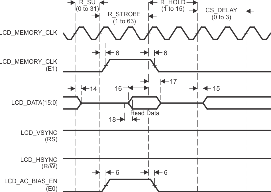
A. Hitachi mode performs asynchronous operations that do not require an external LCD_MEMORY_CLK. The first LCD_MEMORY_CLK waveform is only shown as a reference of the internal clock that sequences the other signals. The second LCD_MEMORY_CLK waveform is shown as E1 because the LCD_MEMORY_CLK signal is used to implement the E1 function in Hitachi mode.
Figure 7-74 Data Read in Hitachi Mode 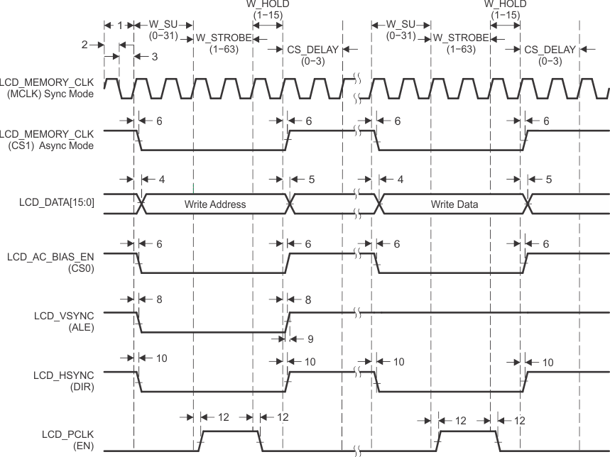
A. Motorola mode can be configured to perform asynchronous operations or synchronous operations. When configured in asynchronous mode, LCD_MEMORY_CLK is not required, so it performs the CS1 function. When configured in synchronous mode, LCD_MEMORY_CLK performs the MCLK function. LCD_MEMORY_CLK is also shown as a reference of the internal clock that sequences the other signals.
Figure 7-75 Micro-Interface Graphic Display Motorola Write 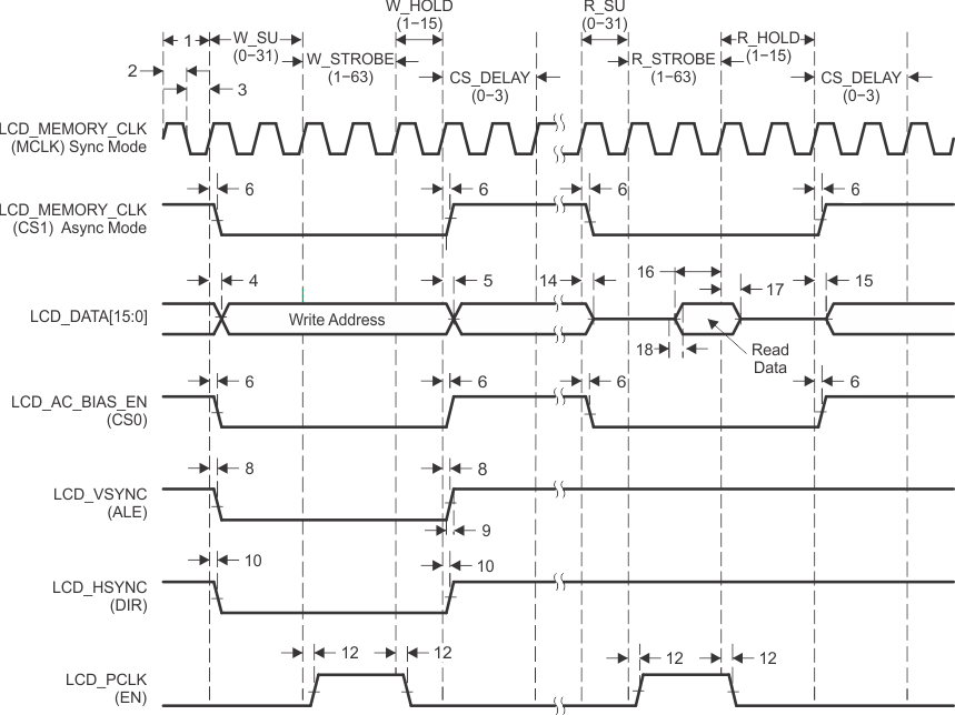
A. Motorola mode can be configured to perform asynchronous operations or synchronous operations. When configured in asynchronous mode, LCD_MEMORY_CLK is not required, so it performs the CS1 function. When configured in synchronous mode, LCD_MEMORY_CLK performs the MCLK function. LCD_MEMORY_CLK is also shown as a reference of the internal clock that sequences the other signals.
Figure 7-76 Micro-Interface Graphic Display Motorola Read 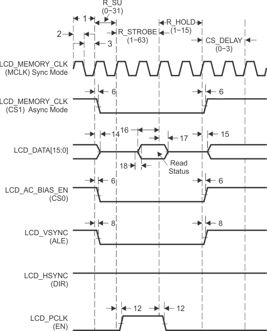
A. Motorola mode can be configured to perform asynchronous operations or synchronous operations. When configured in asynchronous mode, LCD_MEMORY_CLK is not required, so it performs the CS1 function. When configured in synchronous mode, LCD_MEMORY_CLK performs the MCLK function. LCD_MEMORY_CLK is also shown as a reference of the internal clock that sequences the other signals.
Figure 7-77 Micro-Interface Graphic Display Motorola Status 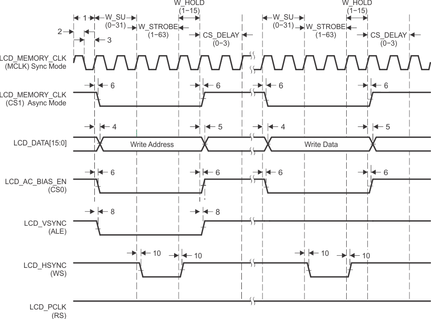
A. Intel mode can be configured to perform asynchronous operations or synchronous operations. When configured in asynchronous mode, LCD_MEMORY_CLK is not required, so it performs the CS1 function. When configured in synchronous mode, LCD_MEMORY_CLK performs the MCLK function. LCD_MEMORY_CLK is also shown as a reference of the internal clock that sequences the other signals.
Figure 7-78 Micro-Interface Graphic Display Intel Write 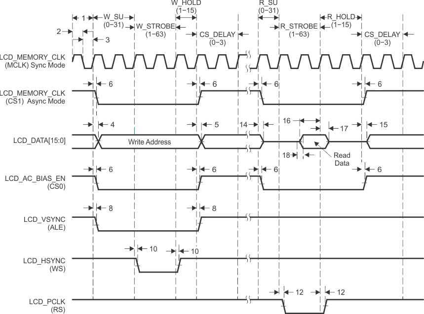
A. Intel mode can be configured to perform asynchronous operations or synchronous operations. When configured in asynchronous mode, LCD_MEMORY_CLK is not required, so it performs the CS1 function. When configured in synchronous mode, LCD_MEMORY_CLK performs the MCLK function. LCD_MEMORY_CLK is also shown as a reference of the internal clock that sequences the other signals.
Figure 7-79 Micro-Interface Graphic Display Intel Read 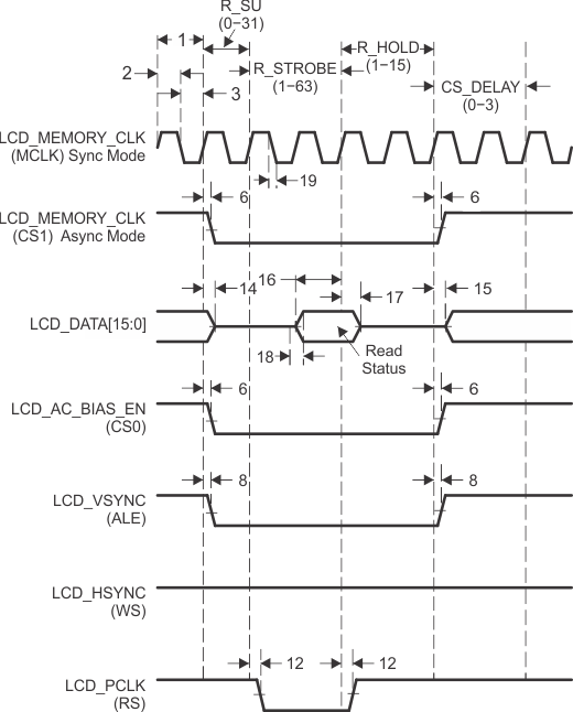
A. Intel mode can be configured to perform asynchronous operations or synchronous operations. When configured in asynchronous mode, LCD_MEMORY_CLK is not required, so it performs the CS1 function. When configured in synchronous mode, LCD_MEMORY_CLK performs the MCLK function. LCD_MEMORY_CLK is also shown as a reference of the internal clock that sequences the other signals.
Figure 7-80 Micro-Interface Graphic Display Intel Status