SPRSP85A April 2024 – September 2024 TMS320F28P550SJ , TMS320F28P559SJ-Q1
PRODMIX
- 1
- 1 Features
- 2 Applications
- 3 Description
- 4 Device Comparison
- 5 Pin Configuration and Functions
-
6 Specifications
- 6.1 Absolute Maximum Ratings
- 6.2 ESD Ratings – Commercial
- 6.3 ESD Ratings – Automotive
- 6.4 Recommended Operating Conditions
- 6.5 Power Consumption Summary
- 6.6 Electrical Characteristics
- 6.7 Special Considerations for 5V Fail-Safe Pins
- 6.8 Thermal Resistance Characteristics for PDT Package
- 6.9 Thermal Resistance Characteristics for PZ Package
- 6.10 Thermal Resistance Characteristics for PNA Package
- 6.11 Thermal Resistance Characteristics for PM Package
- 6.12 Thermal Resistance Characteristics for RSH Package
- 6.13 Thermal Design Considerations
- 6.14
System
- 6.14.1
Power Management Module (PMM)
- 6.14.1.1 Introduction
- 6.14.1.2 Overview
- 6.14.1.3 External Components
- 6.14.1.4 Power Sequencing
- 6.14.1.5 Power Management Module Electrical Data and Timing
- 6.14.2 Reset Timing
- 6.14.3
Clock Specifications
- 6.14.3.1 Clock Sources
- 6.14.3.2
Clock Frequencies, Requirements, and Characteristics
- 6.14.3.2.1
Input Clock Frequency and Timing
Requirements, PLL Lock Times
- 6.14.3.2.1.1 Input Clock Frequency
- 6.14.3.2.1.2 XTAL Oscillator Characteristics
- 6.14.3.2.1.3 X1 Input Level Characteristics When Using an External Clock Source - Not a Crystal
- 6.14.3.2.1.4 X1 Timing Requirements
- 6.14.3.2.1.5 AUXCLKIN Timing Requirements
- 6.14.3.2.1.6 APLL Characteristics
- 6.14.3.2.1.7 XCLKOUT Switching Characteristics - PLL Bypassed or Enabled
- 6.14.3.2.1.8 Internal Clock Frequencies
- 6.14.3.2.1
Input Clock Frequency and Timing
Requirements, PLL Lock Times
- 6.14.3.3 Input Clocks and PLLs
- 6.14.3.4 XTAL Oscillator
- 6.14.3.5 Internal Oscillators
- 6.14.4 Flash Parameters
- 6.14.5 RAM Specifications
- 6.14.6 ROM Specifications
- 6.14.7 Emulation/JTAG
- 6.14.8 GPIO Electrical Data and Timing
- 6.14.9 Interrupts
- 6.14.10
Low-Power Modes
- 6.14.10.1 Clock-Gating Low-Power Modes
- 6.14.10.2
Low-Power Mode Wake-up Timing
- 6.14.10.2.1 IDLE Mode Timing Requirements
- 6.14.10.2.2 IDLE Mode Switching Characteristics
- 6.14.10.2.3 IDLE Entry and Exit Timing Diagram
- 6.14.10.2.4 STANDBY Mode Timing Requirements
- 6.14.10.2.5 STANDBY Mode Switching Characteristics
- 6.14.10.2.6 STANDBY Entry and Exit Timing Diagram
- 6.14.10.2.7 HALT Mode Timing Requirements
- 6.14.10.2.8 HALT Mode Switching Characteristics
- 6.14.10.2.9 HALT Entry and Exit Timing Diagram
- 6.14.1
Power Management Module (PMM)
- 6.15
Analog Peripherals
- 6.15.1 Block Diagram
- 6.15.2 Analog Pins and Internal Connections
- 6.15.3 Analog Signal Descriptions
- 6.15.4 Analog-to-Digital Converter (ADC)
- 6.15.5 Temperature Sensor
- 6.15.6
Comparator Subsystem (CMPSS)
- 6.15.6.1 CMPx_DACL
- 6.15.6.2 CMPSS Connectivity Diagram
- 6.15.6.3 Block Diagram
- 6.15.6.4
CMPSS Electrical Data and Timing
- 6.15.6.4.1 CMPSS Comparator Electrical Characteristics
- CMPSS Comparator Input Referred Offset and Hysteresis
- 6.15.6.4.2 CMPSS DAC Static Electrical Characteristics
- 6.15.6.4.3 CMPSS Illustrative Graphs
- 6.15.6.4.4 Buffered Output from CMPx_DACL Operating Conditions
- 6.15.6.4.5 Buffered Output from CMPx_DACL Electrical Characteristics
- 6.15.7 Buffered Digital-to-Analog Converter (DAC)
- 6.15.8 Programmable Gain Amplifier (PGA)
- 6.16 Control Peripherals
- 6.17
Communications Peripherals
- 6.17.1 Modular Controller Area Network (MCAN)
- 6.17.2 Inter-Integrated Circuit (I2C)
- 6.17.3 Power Management Bus (PMBus) Interface
- 6.17.4 Serial Communications Interface (SCI)
- 6.17.5 Serial Peripheral Interface (SPI)
- 6.17.6 Local Interconnect Network (LIN)
- 6.17.7 Fast Serial Interface (FSI)
- 6.17.8 Universal Serial Bus (USB)
-
7 Detailed Description
- 7.1 Overview
- 7.2 Functional Block Diagram
- 7.3 Memory
- 7.4 Identification
- 7.5 Bus Architecture – Peripheral Connectivity
- 7.6 C28x Processor
- 7.7 Control Law Accelerator (CLA)
- 7.8 Embedded Real-Time Analysis and Diagnostic (ERAD)
- 7.9 Direct Memory Access (DMA)
- 7.10 Device Boot Modes
- 7.11 Security
- 7.12 Watchdog
- 7.13 C28x Timers
- 7.14 Dual-Clock Comparator (DCC)
- 7.15 Configurable Logic Block (CLB)
- 8 Reference Design
- 9 Device and Documentation Support
- 10Revision History
- 11Mechanical, Packaging, and Orderable Information
6.14.4 Flash Parameters
Table 6-6 lists the minimum required Flash wait states with different clock sources and frequencies. Wait state is the value set in register FRDCNTL[RWAIT].
| CPUCLK (MHz) | Wait States (FRDCNTL[RWAIT](1)) |
|---|---|
| 120 < CPUCLK ≤ 150 | 3 |
| 80 < CPUCLK ≤ 120 | 2 |
| 0 < CPUCLK ≤ 80 | 1 |
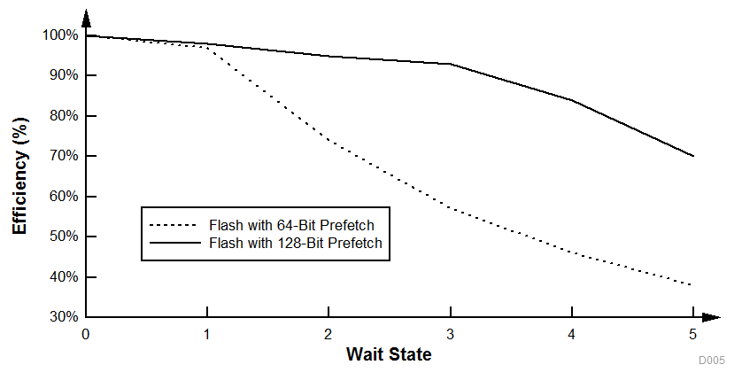
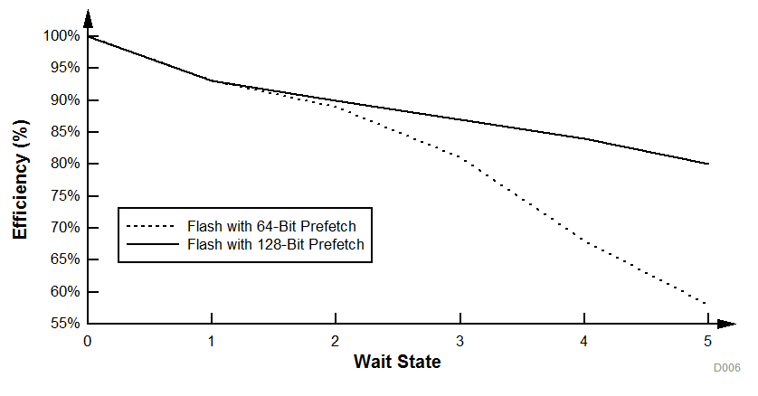
The F28P55x devices have a 128-bit prefetch buffer that provides high flash code execution efficiency across wait states. Figure 6-18 and Figure 6-19 illustrate typical efficiency across wait-state settings compared to previous-generation devices with a 64-bit prefetch buffer. Wait-state execution efficiency with a prefetch buffer will depend on how many branches are present in application software. Two examples of linear code and if-then-else code are provided.
 Figure 6-18 Application Code With Heavy 32-Bit Floating-Point Math Instructions
 Figure 6-19 Application Code With 16-Bit If-Else Instructions
The Main Array flash programming must be aligned to 64-bit address boundaries and each 64-bit word may only be programmed once per write/erase cycle.