SPRUHW1A June   2014  – October 2021 TMS320F28052-Q1 , TMS320F28052M , TMS320F28052M-Q1 , TMS320F28054-Q1 , TMS320F28054M , TMS320F28054M-Q1


  1. 1Read This First
    1. 1.1 About This Manual
    2. 1.1 Glossary
    3. 1.1 Support Resources
    4.     Trademarks
  2. 1 F2805xM InstaSPIN-MOTION Enabled MCUs
  3. 2InstaSPIN-MOTION Key Capabilities and Benefits
    1. 2.1 Overview
    2. 2.2 FAST Unified Observer
    3. 2.3 SpinTAC Motion Control Suite
      1.      IDENTIFY
      2.      CONTROL
      3.      MOVE
      4.      PLAN
    4. 2.4 Additional InstaSPIN-MOTION Features
  4. 3InstaSPIN-MOTION Block Diagrams
    1.     Scenario 1: InstaSPIN-MOTION Speed Control with FAST Software Encoder
    2.     Scenario 2: InstaSPIN-MOTION Speed Control with a Mechanical Sensor
    3.     Scenario 3: InstaSPIN-MOTION Position Control with Mechanical Sensor and Redundant FAST Software Sensor
  5. 4Application Examples
    1. 4.1 Treadmill Conveyor: Smooth Motion Across Varying Speeds and Loads
    2. 4.2 Video Camera: Smooth Motion and Position Accuracy at Low Speeds
    3. 4.3 Washing Machine: Smooth Motion and Position Accuracy at Low Speeds
      1.      Agitation Cycle
      2.      Spin Cycles
    4. 4.4 InstaSPIN-MOTION Works Over the Entire Operating Range
  6. 5Evaluating InstaSPIN-MOTION Performance
    1. 5.1 Overview
    2. 5.2 Velocity Control Performance: SpinTAC vs PI
      1. 5.2.1 Disturbance Rejection
      2. 5.2.2 Reference Tracking
      3. 5.2.3 Step Response
    3. 5.3 Position Control Performance: SpinTAC vs PI
      1. 5.3.1 Disturbance Rejection
      2. 5.3.2 Reference Tracking
      3. 5.3.3 Step Response
      4. 5.3.4 Inertia Estimation Repeatability
  7. 6Microcontroller Resources
    1. 6.1 CPU Utilization
    2. 6.2 Memory Utilization
    3. 6.3 Security Zones
    4. 6.4 Linker Command File Settings
    5. 6.5 Interfacing FAST ROM Libraries
    6. 6.6 Pin Utilization
    7. 6.7 Consideration of Analog Front-End (AFE) Module
      1. 6.7.1 Routing Current Signals
      2. 6.7.2 Voltage Reference Connection
      3. 6.7.3 Routing Voltage Signals
        1.       A Resources
          1.        B Definition of Terms and Acronyms
            1.         C Revision History

Spin Cycles

For the first spin cycle, the objective is to maintain 500 rpm, even when disturbances are introduced. Figure 5-3 shows that InstaSPIN-MOTION recovered from disturbances more quickly, and with less oscillation, than the PI controller. Additionally, InstaSPIN-MOTION does not suffer from the overshoot and undershoot shown by the PI controller when it tries to reach the initial 500 rpm setpoint.

GUID-DEEDD83B-9FD7-41C8-9E20-0105E0A2710D-low.gif Figure 4-3 First Spin Cycle - 500 rpm


During the second spin cycle, shown in Figure 5-4, the SpinTAC controller consistently recovered from disturbances at 2000 rpm more quickly, and with less oscillation, than the PI controller. Note that SpinTAC does not suffer from the overshoot and undershoot shown by the PI controller when it tries to reach the initial 2000 rpm setpoint.
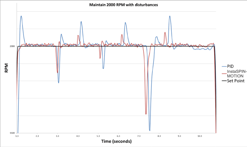
GUID-9E581A0A-6869-48BC-8BE3-D37CD2718CDC-low.gif Figure 4-4 Second Spin Cycle - 2000 rpm


Additionally, the PI controller could not recover from the ramp disturbance at the 9.75 second mark. Instead, it shows a steady-state error of roughly 20 rpm.