SPRUIS8A january 2020 – august 2023 DRA829J , DRA829J-Q1 , DRA829V , DRA829V-Q1 , TDA4VM , TDA4VM-Q1
- 1
- Trademarks
- 1Introduction
- 2Step 1: Setup EVM and Expansion Card Hardware
- 3Step 2: Experiencing the Out Of Box (OOB) Demonstration to Ensure the EVM Hardware is Functional
- 4Step 3: Download and Install Processor SDK (softweare development kit)
- 5Step 4: Project 0, Your First ‘Hello World’ project to Ensure Interoperability of EVM and Software
- Additional Resources
- A Installing the Automotive Gateway/Ethernet Switch/Industrial Expansion Card Onto the Common Processor Board
- B Installing the Infotainment Expansion Board Onto the Common Processor Board
- Revision History
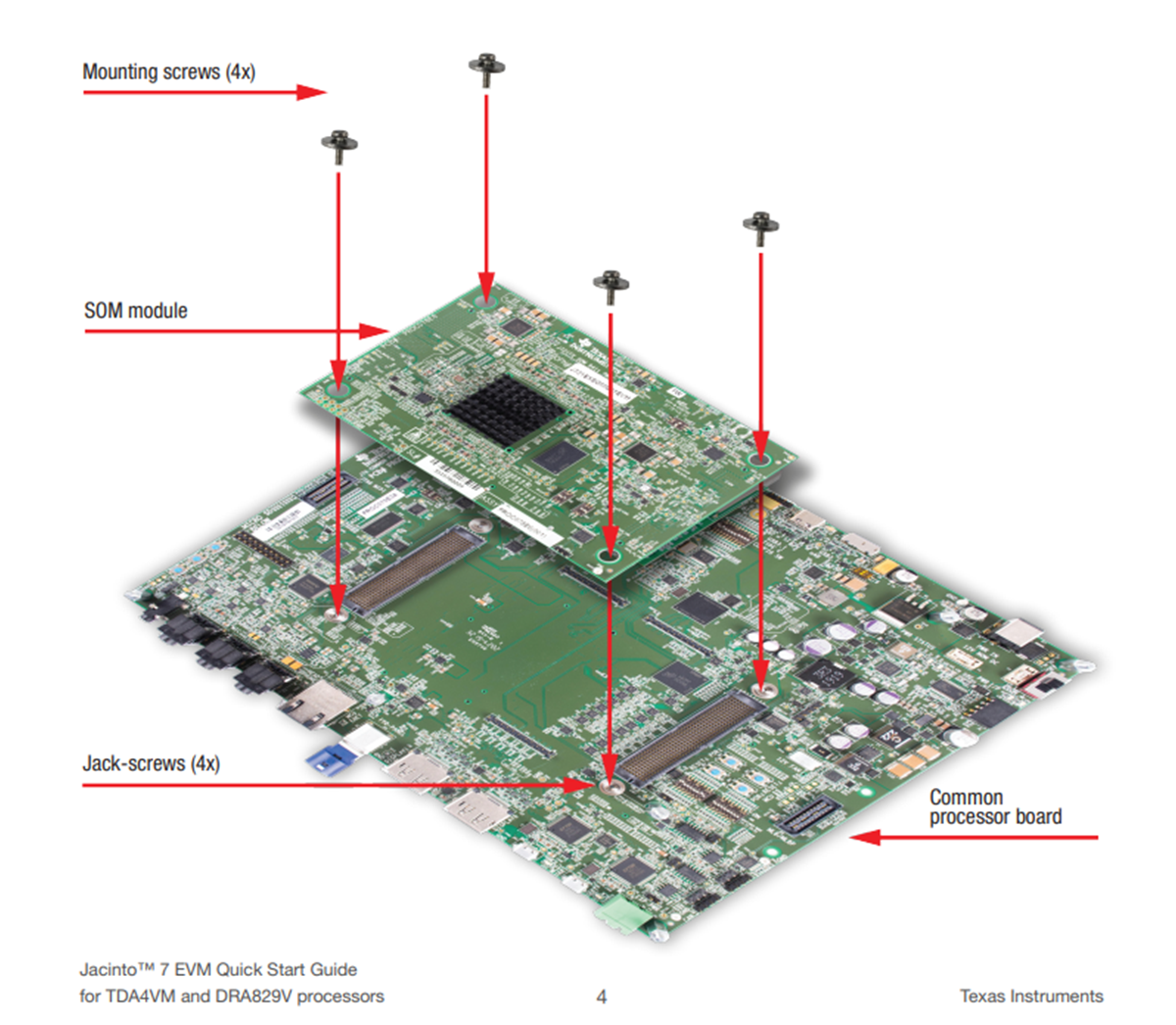
2.1 Attaching the SOM to the Common Processor Board
- Remove mounting screws (4) from Common Processor board (sold separately). The screws are shipped installed in jack-screws. If existing SOM module is already mounted, use Allen wrench (supplied with SOM) to eject SOM module by inserting the wrench into each jack-screw and turning counter-clockwise at each location until SOM module is loose.
- Before installing new SOM, make sure all jack-screws are tight by inserting the wrench and turning clockwise at each location.
- Install the SOM module on the Common Processor Board. Ensure it is oriented such that all connectors are aligned. Press firmly on the edges to ensure the connectors mate (may have to apply significant pressure).
- Install mounting screws (4x) in
each corner of the SOM (see below). Tighten each screw to ensure all connectors
are fully mated. Don’t over-tighten.
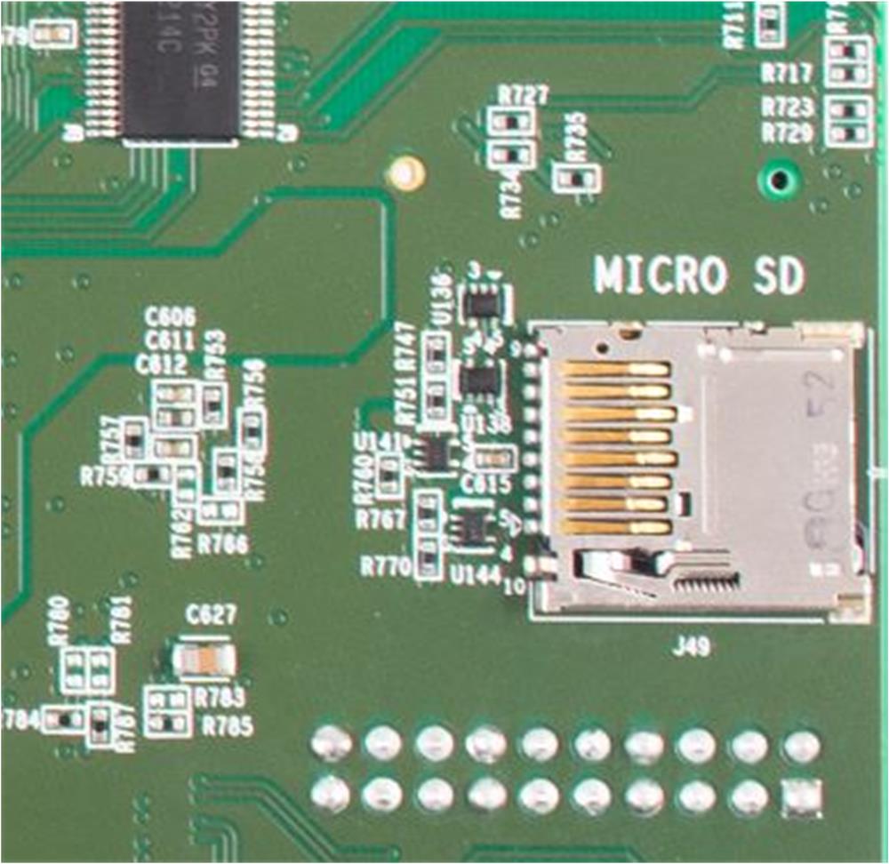
- Insert
the supplied Linux SD card into the Micro SD card slot (see below). The location
of the card slot is on the backside of the Common Processor Board.
- Connect the supplied USB cable to
the USB/Serial Debug connector as shown. Connect other end to PC. Launch a
terminal program (example, TeraTerm) and connect to first of four UARTs that are
assigned to USB port. Set terminal to operate at Baud 115200, 8b no parity, and
flow control off.
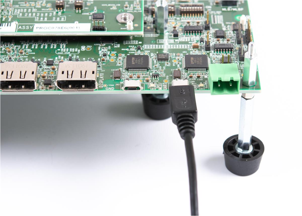
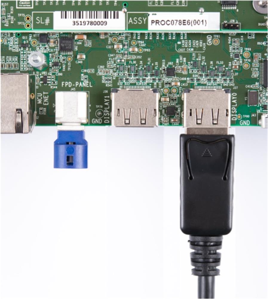
- If a
DisplayPort panel is available (not included), connect the supplied DisplayPort
cable to the EVM as shown. Connect other end to DisplayPort panel. If no panel
is available, this step can be skipped.
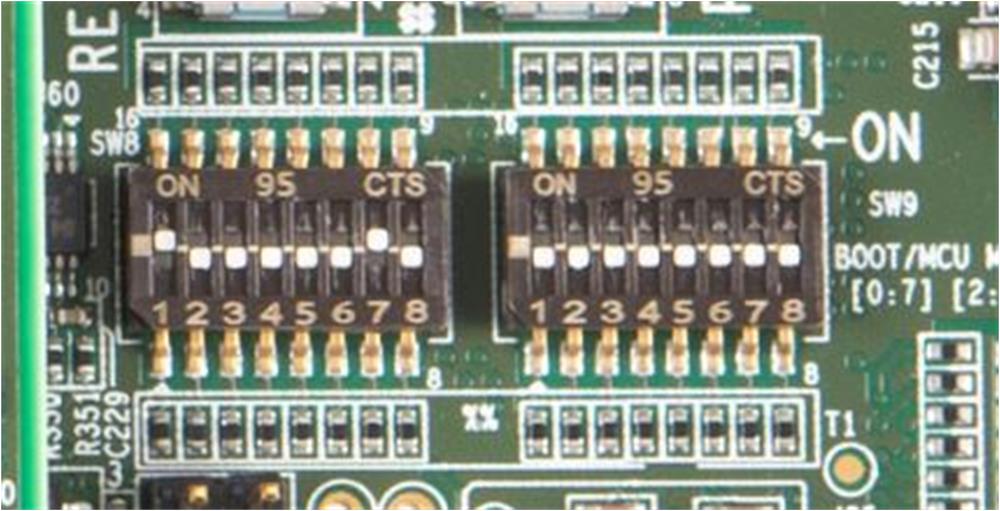
- Confirm the boot configuration
switches SW8 and SW9 are set as shown.
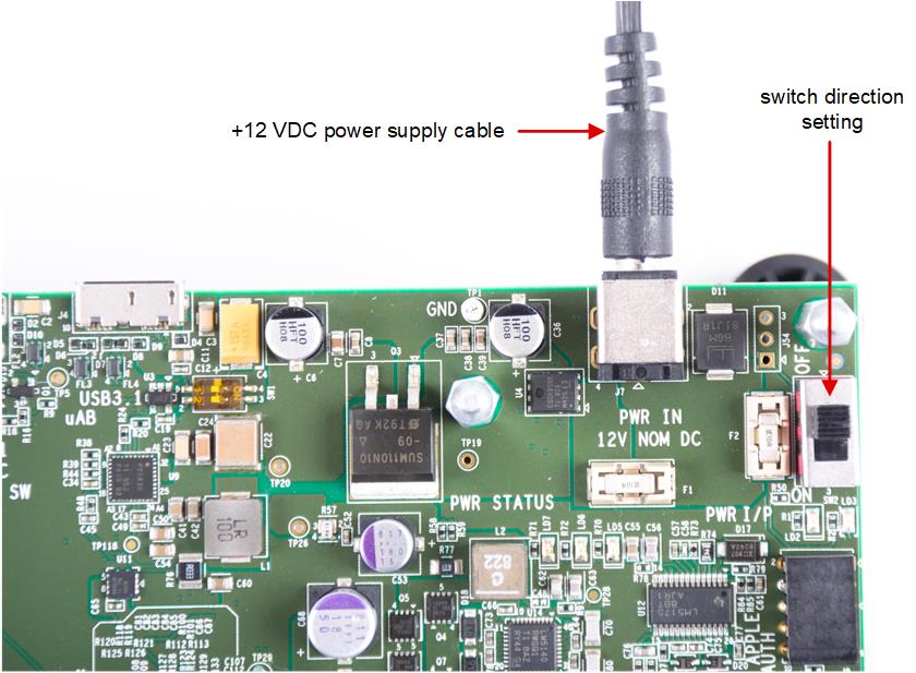
- Connect a +12 VDC power supply (not included) with minimum output rating of 5 Amp, positive inner and negative outer terminals, female barrel 5.5 mm x 2.5 mm. Recommended power supply is CUI Inc. SDI65-12-U-P6 or equivalent.
- To turn EVM system on, set switch
SW2 to the ‘ON’ position. To turn EVM off, set switch SW2 to ‘OFF’.