SPRUIT8D February 2020 – February 2021 AWR2243
- Trademarks
- 1Getting Started
- 2Hardware
- 3Design Files and Software Tools
- 4Design Revision History
- 5Mechanical Mounting of PCB
- 6PCB Storage and Handling Recommendations
- 7Regulatory Information
- 8Revision History
2.4.2 60-Pin High Density (HD) Connector
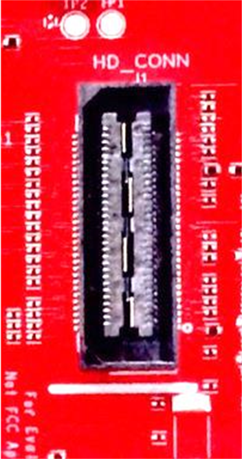
The 60-pin HD connector provides high speed data over CSI or the HS_DEBUG interface, and controls signals (SPI, UART, I2C, NRST, NERR, and SOPs) and JTAG debug signals (see Table 2-3). This connector can be connected to the MMWAVE-DEVPACK board and interface with the TSW1400 (see Figure 2-7).
 Figure 2-7 High Density Connector (60 Pin)
| Pin Number | Description | Pin Number | Description |
|---|---|---|---|
| 1 | 5 V | 2 | 5 V |
| 3 | 5 V | 4 | TDO |
| 5 | TDI | 6 | TCK |
| 7 | SPI_CS | 8 | TMS |
| 9 | SPI_CLK | 10 | HOSTINT |
| 11 | SPI_MOSI | 12 | SPI_MISO |
| 13 | PGOOD (onboard VIO) | 14 | NERROUT |
| 15 | NC | 16 | SYNC_IN |
| 17 | NC | 18 | GND |
| 19 | NC | 20 | DEBUG_VALIDP |
| 21 | NC | 22 | DEBUG_VALIDM |
| 23 | NC | 24 | GND |
| 25 | NC | 26 | DEBUG_FRCLKP |
| 27 | NC | 28 | DEBUG_FRCLKM |
| 29 | NC | 30 | GND |
| 31 | NC | 32 | DEBUG/CSI_3P |
| 33 | NC | 34 | DEBUG/CSI_3M |
| 35 | NC | 36 | GND |
| 37 | NC | 38 | DEBUG/CSI_2P |
| 39 | NC | 40 | DEBUG/CSI_2M |
| 41 | NC | 42 | GND |
| 43 | NC | 44 | DEBUG/CSI_CLKP |
| 45 | NC | 46 | DEBUG/CSI_CLKM |
| 47 | NC | 48 | GND |
| 49 | NC | 50 | DEBUG/CSI_1P |
| 51 | I2C_SDA | 52 | DEBUG/CSI_1M |
| 53 | I2C_SCL | 54 | GND |
| 55 | RS232RX (Rx into AWR device) | 56 | DEBUG/CSI_0P |
| 57 | RS232TX (Tx from AWR device) | 58 | DEBUG/CSI_0M |
| 59 | nRESET | 60 | GND |
PGOOD – This signal indicates that the state of the onboard VIO supply for the AWR device coming from the onboard PMIC. A high on the PGOOD signal (3.3 V) indicates the supply is stable. Because the I/Os are not failsafe, the MCU must ensure that it does not drive any I/O signals to the AWR device before this I/O supply is stable, to avoid leakage current into the I/Os.