-
AWR2944/AWR2944P Evaluation Module
- 1
- Description
- Features
- 4
- 1Evaluation Module Overview
-
2Hardware
- 2.1 Block Diagram
- 2.2 PCB Handling Recommendations
- 2.3 Power Connections
- 2.4
Connectors
- 2.4.1 MIPI 60-Pin Connector (J19)
- 2.4.2 Debug Connector-60 pin (J7)
- 2.4.3 CAN-A Interface Connector (J3)
- 2.4.4 CAN-B Interface Connector (J2)
- 2.4.5 Ethernet Ports (J4 and J9)
- 2.4.6 USB Connectors (J8, J10)
- 2.4.7 OSC_CLKOUT Connector (J14)
- 2.4.8 PMIC SPI Connector (J16) (DNP)
- 2.4.9 Voltage Rails Ripple Measurement Connectors (J1, J5) (DNP)
- 2.5 Antenna
- 2.6 PMIC
- 2.7 On-Board Sensors
- 2.8 PC Connection
- 2.9 Connecting the AWR2944EVM/AWR2944PEVM to the DCA1000 EVM
- 2.10 Jumpers, Switches, and LEDs
- 3Software
- 4Hardware Design Files
- 5Compliance Information
- 6Additional Information
- 7Revision History
- IMPORTANT NOTICE
EVM User's Guide
AWR2944/AWR2944P Evaluation Module
Description
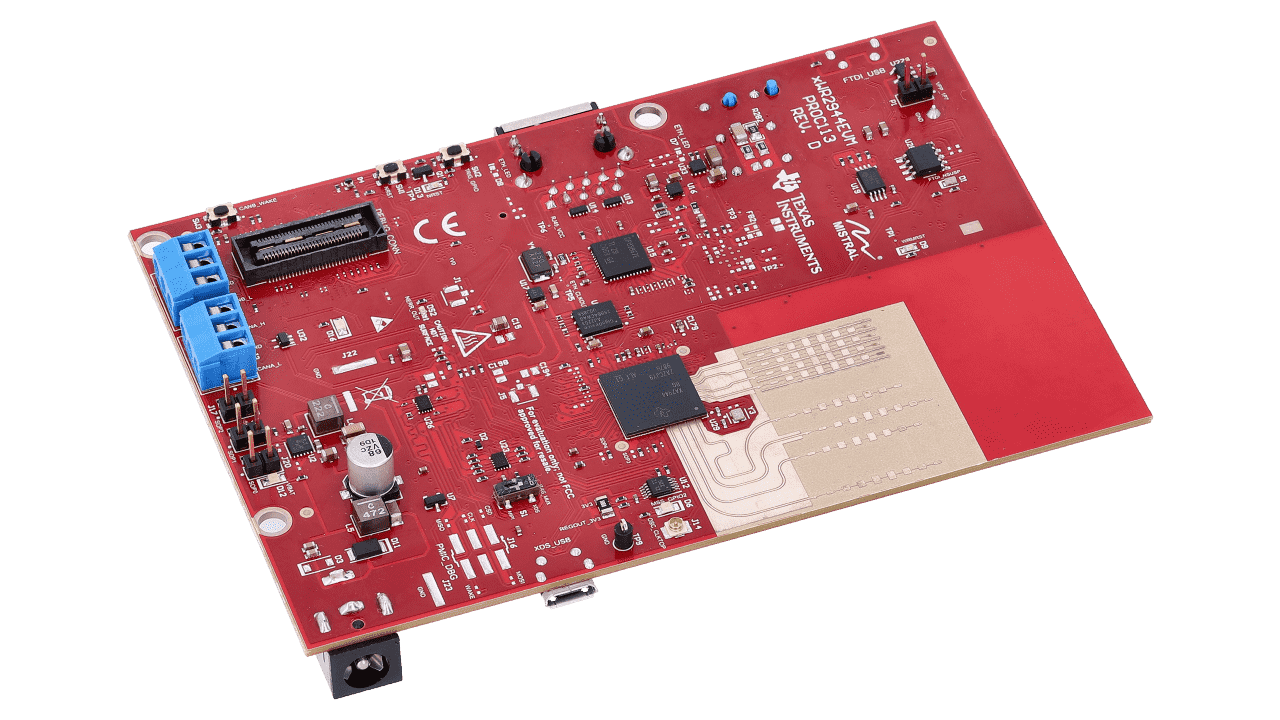
The AWR2944/AWR2944P evaluation module (EVM) is an easy-to-use platform for evaluating the AWR2944/AWR2944P mmWave system-on-chip (SoC) radar sensor, which has direct connectivity to the DCA1000EVM (sold separately). The AWR2944EVM/AWR2944PEVM kit contains everything required to start developing software for the on-chip C66x digital signal processor (DSP), ARM® Cortex®-R5F controller, and hardware accelerator (HWA 2.0 in AWR2944, HWA 2.1 in AWR2944P). Also included is onboard emulation for programming and debugging, as well as onboard buttons and LEDs for quick integration of a simple user interface.
Features
- 76GHz to 81GHz mmWave radar sensor
- Onboard four-transmit four-receive (4TX/4RX) antenna
- On-chip C66x DSP core and Arm Cortex-R5F controller
- On-chip hardware accelerator (HWA 2.0)
- Direct interface with DCA1000EVM
 AWR2944EVM