SPRUJ22C November 2021 – September 2024 AWR2944 , AWR2944P
- 1
- Description
- Features
- 4
- 1Evaluation Module Overview
-
2Hardware
- 2.1 Block Diagram
- 2.2 PCB Handling Recommendations
- 2.3 Power Connections
- 2.4
Connectors
- 2.4.1 MIPI 60-Pin Connector (J19)
- 2.4.2 Debug Connector-60 pin (J7)
- 2.4.3 CAN-A Interface Connector (J3)
- 2.4.4 CAN-B Interface Connector (J2)
- 2.4.5 Ethernet Ports (J4 and J9)
- 2.4.6 USB Connectors (J8, J10)
- 2.4.7 OSC_CLKOUT Connector (J14)
- 2.4.8 PMIC SPI Connector (J16) (DNP)
- 2.4.9 Voltage Rails Ripple Measurement Connectors (J1, J5) (DNP)
- 2.5 Antenna
- 2.6 PMIC
- 2.7 On-Board Sensors
- 2.8 PC Connection
- 2.9 Connecting the AWR2944EVM/AWR2944PEVM to the DCA1000 EVM
- 2.10 Jumpers, Switches, and LEDs
- 3Software
- 4Hardware Design Files
- 5Compliance Information
- 6Additional Information
- 7Revision History
2.5 Antenna
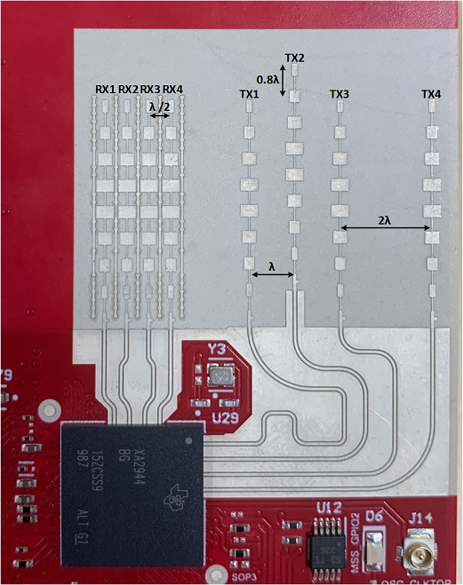
The AWR2944EVM/AWR2944PEVM includes etched antennas onboard for the four receivers and four transmitters, which enables tracking multiple objects with the distance and angle information. This antenna design enables estimation of both azimuth and elevation angles, which enables object detection in a 3D plane (see Figure 2-17).
 Figure 2-17 AWR2944EVM Antenna
Design
Figure 2-17 AWR2944EVM Antenna
DesignThe antenna placement shown in Figure 2-17 results in the virtual antenna array shown in Figure 2-18.
 Figure 2-18 Virtual Antenna Array
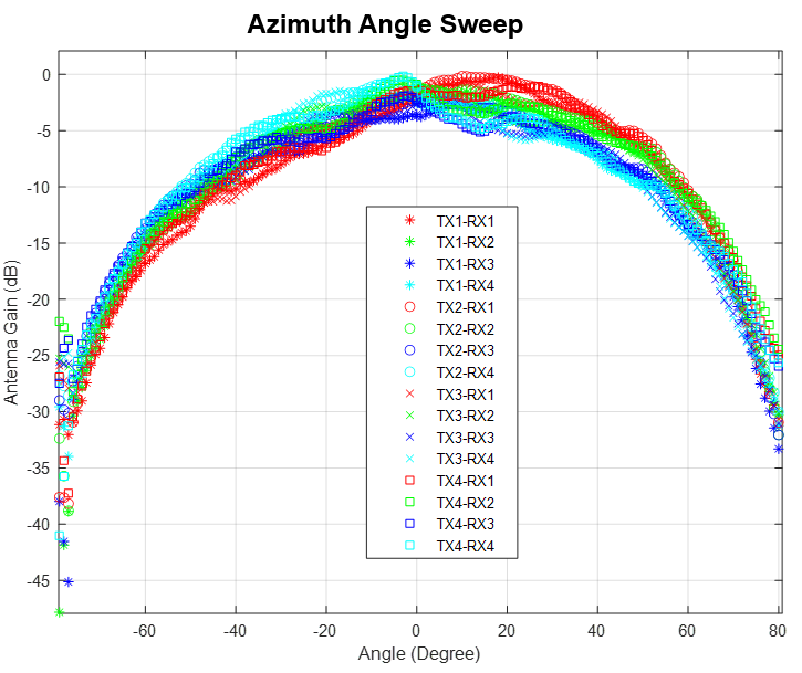
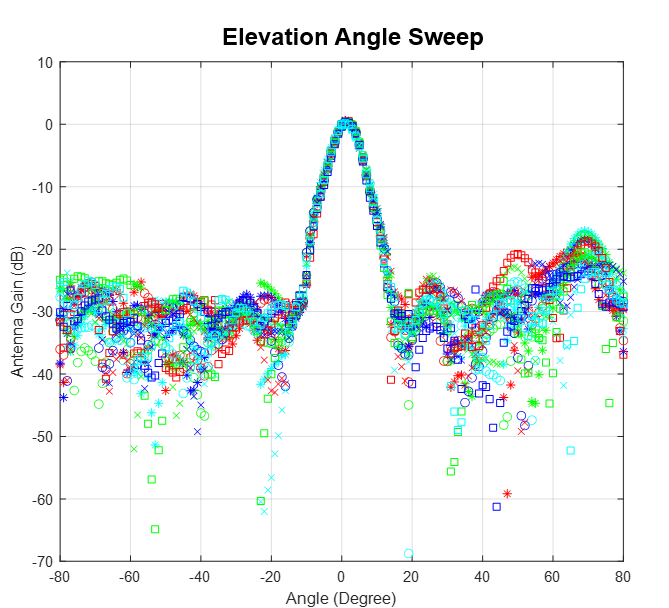
The antenna peak gain is 13dBi across the frequency band of 76 to 81GHz. The radiation pattern of the antenna in the horizontal plan (H-plane) and elevation plan (E-plane) is as shown in Figure 2-19 and Figure 2-20, respectively.
The beamwidth of the antenna design can be determined from the radiation patterns provided below. For example, based on 3dB drop in the gain as compared to bore sight, the horizontal 3dB-beamwidth is approximately ±30 degrees (see Figure 2-19), and elevation 3dB-beamwidth is approximately ±3 degrees (see Figure 2-20). Similarly, the horizontal 6dB beamwidth is approximately ±45 degrees (see Figure 2-19) and the elevation 6dB-beamwidth is approximately ±5 degrees (see Figure 2-20).
 Figure 2-19 Azimuth Radiation Pattern
 Figure 2-20 Elevation Radiation Pattern