SPRUJ97 June 2024
- 1
- Description
- Get Started
- Features
- Applications
- 6
- 1Evaluation Module Overview
- 2Hardware
- 3Hardware Design Files
- 4Compliance Information
- 5Additional Information
- 6Related Documentation
2.1 Key Features and Interfaces
The J7EXPA01EVM is a add-on module that expands the feature set of select TI processor evaluation modules (EVMs) to include advanced video capture features. The combined EVM design provides users the ability to evaluate and develop automotive and industrial applications that utilize advanced video and image processing. A summary of features included with this expansion EVM include:
- Supported on multiple Texas Instruments Processor EVMs
- Up to 12 total image sensor or data input ports; each supporting up to 8MP sensors /40 FPS. (Depending on the capability of the base EVM, the number of supported inputs can vary)
- Utilizes Texas Instruments' FPD-Link IV technology, can be paired with sensors supporting DS90UB953 or DS90UB971 serializers
- Each deserializer hub aggregates data from up to 4 sensors onto single MIPI CSI2 port
- Includes both Coax and STP configurations
- Support power-over-coax for powering remote sensors
- Provides supplemental power input for higher power configurations
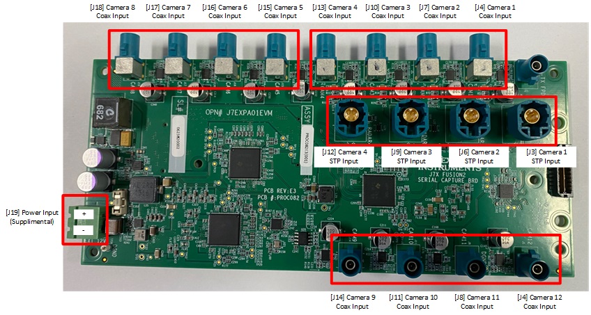
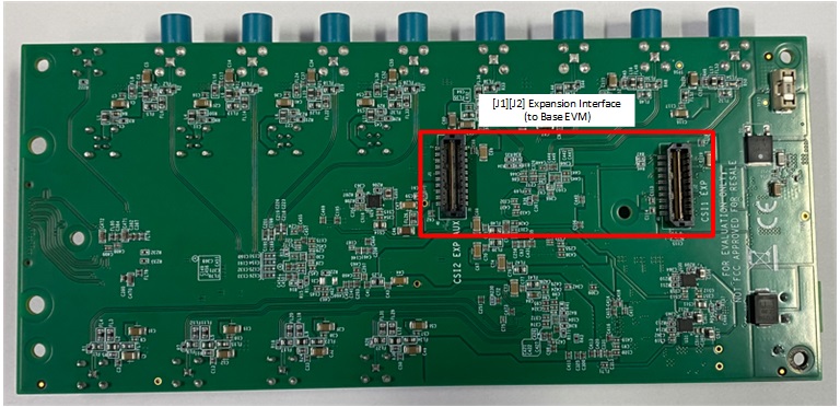
The EVM images identify the locations of key features and user interfaces (top and bottom view).
 Figure 2-1 Key Features and Interfaces
(Top)
 Figure 2-2 Key Features and Interfaces
(Bottom)