SPRUJ97 June 2024
- 1
- Description
- Get Started
- Features
- Applications
- 6
- 1Evaluation Module Overview
- 2Hardware
- 3Hardware Design Files
- 4Compliance Information
- 5Additional Information
- 6Related Documentation
2.3 Assembly Instructions
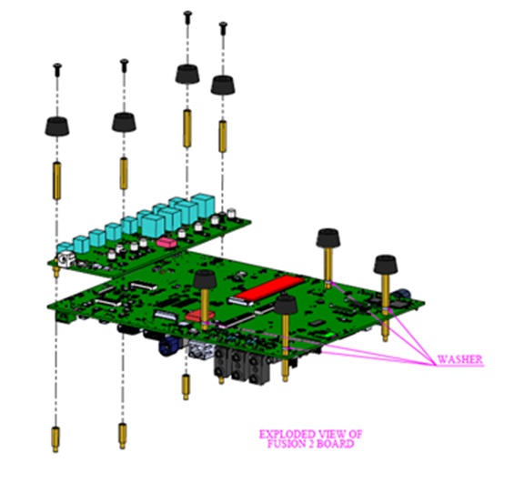
For assembly of the J7EXPA01EVM add-on module with the J721EXCPXEVM and J784S4XEVM systems, follow the instructions and illustration below.
- If assembling with previously used base EVM, then make sure all power cables and other accessory cables are removed. The EVM must be configured similar to as originally delivered.
- Orient the EVM such that the processor is facing downward. The expansion connectors of the EVM must be facing upward.
- Remove the four stand-offs in the area of expansion connector to the washer, leaving the threaded stand-off still attached.
- Install the J7EXPA01EVM module by aligning the mounting holes and mating connectors. Press firmly to make sure the connectors are seated.
- Re-install the four removed stand-offs, but
without the thin washer.Note: The washer is to help level the board accounting for an expansion board PCB thickness.
 Figure 2-3 Assembly Illustration