SPRUJA2 November 2023
- 1
- Description
- Get Started
- Features
- 5
- 1Evaluation Module Overview
-
2Hardware
- 2.1 Additional Images
- 2.2 Key Features
- 2.3 Interface Mapping
- 2.4 Power ON/OFF Procedure
- 2.5 Clocking
- 2.6 Reset
- 2.7 CSI Interface
- 2.8 OLDI Interface
- 2.9 DSI Interface
- 2.10 Audio Codec Interface
- 2.11 HDMI Display Interface
- 2.12 JTAG Interface
- 2.13 Test Automation Header
- 2.14 UART Interface
- 2.15 USB Interface
- 2.16 Memory Interfaces
- 2.17 Ethernet Interface
- 2.18 GPIO Port Expander
- 2.19 GPIO Mapping
- 2.20 Power
- 2.21 EVM User Setup/Configuration
- 2.22 Expansion Headers
- 2.23 Interrupt
- 2.24 I2C Address Mapping
- 3Hardware Design Files
- 4Compliance Information
- 5Additional Information
2.20.3 Power Supply
AM62P SK EVM utilizes an array of DC-DC converters to supply the various memories, clocks, SOC and other components/peripherals on the board with the necessary voltage and the power required.
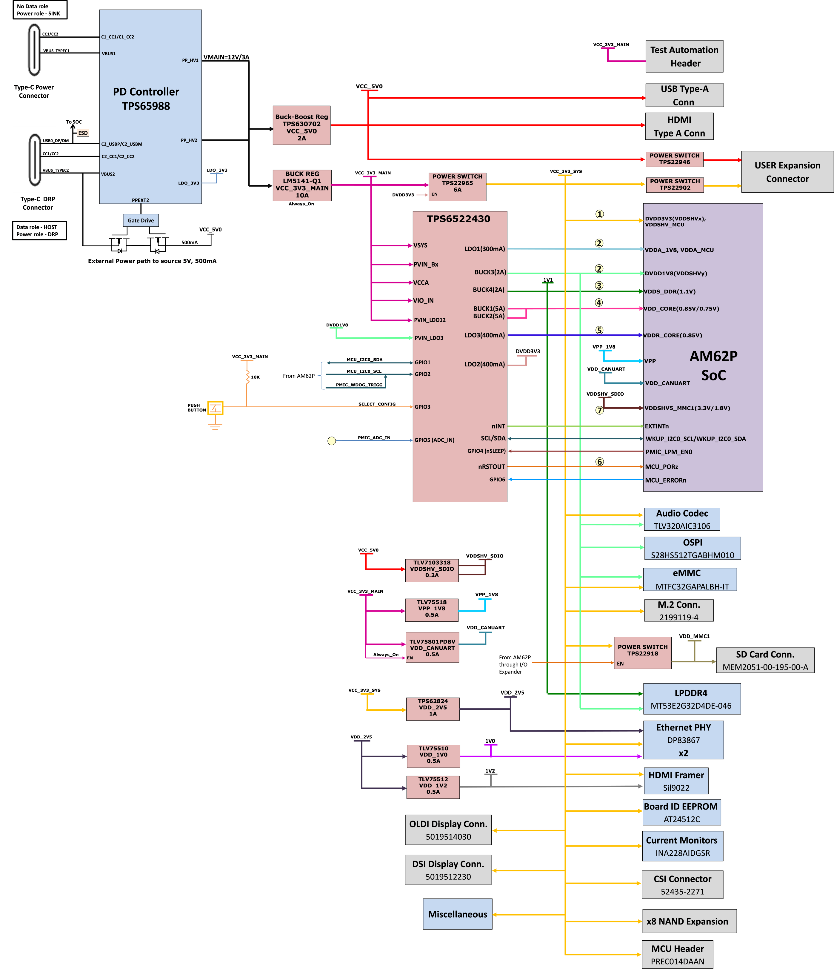
The figure below figure shows the various discrete regulators, PMIC and LDOs used to source power rails for each peripheral on AM62P SK EVM.
 Figure 2-25 Power Architecture
The following sections describe the power distribution network topology that supplies the SK EVM board, supporting components and reference voltages.
The AM62P SK EVM includes a power design based on discrete power supply components. The initial stage of the power supply is VBUS voltage from either of the two USB Type C connectors J17 and J19. USB Type-C Dual PD controller of Mfr. Part# TPS65988DHRSHR is used for negotiation of the required power to the system.
Buck-Boost controller TPS630702RNMR and Buck converter LM5141-Q1 are used for the generation of 5 V and 3.3V respectively and the input to the regulators is the PD output, VMAIN. These 3.3V and 5 V are the primary voltages for the AM62P SK EVM board power resources. The 3.3V supply generated from the Buck regulator LM5141-Q1 is the input supply to the PMIC, various SOC regulators and LDOs. The 5 V supply generated from the Buck Boost regulator TPS630702RNMR is used for powering the onboard peripherals.
Discrete regulators and LDOs used on board are:
- TPS62824DMQR– To generate VDD_2V5 rail for Ethernet PHYs
- TLV75510PDQNR– To generate VDD_1V0 for Ethernet PHYs
- TLV75512PDQNR– To generate VDD_1V2 for HDMI Framer
- PTPS6522430RAHRQ1 (PMIC) – To generate various SOC and Peripheral supplies
- TLV75801PDBVT LDO - VDD_CANUART power of SOC
- TPS79601LDO - XDS110 On board emulator
- TPS73533LDO - FT4232 UART to USB Bridge
- TLV7103318 LDO - To generate VDDSHV5_MMC1 (SD interface) supply for SOC
- TLV75518 LDO - e-Fuse programming of SOC
Additionally,GPIO (TEST_POWERDOWN) is connected to the ENABLE pin of PMIC to control ON/OFF of the SK EVM via XDS110/Test automation. GPIO also disables the VCC_5V0 output of TPS630702RNMR from which several other power supplies are derived.