SPRUJA8A January 2024 – September 2024
2.6.1.1 Industrial Ethernet PHY
The AM2x EVM Industrial Ethernet PHY Add-on Board uses one port of RGMII signals and the PRUx core of the PRU-ICSS to be connected to a 32-pin Ethernet PHY (DP83826ERHBT). The PHY is configured to advertise 10/100 Mb operation. The Ethernet data signals of the PHY are terminated to an RJ45 Connector. LEDs are used to indicate link status and activity.
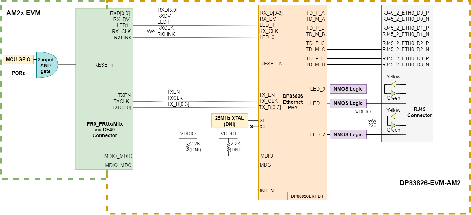
The Ethernet PHY requires two power sources, VDDIO (3.3V or 1.8V) and VDDA3V3 (3.3V) which are supplied through the DF40GB connector (J2).
On some AM2x EVMs, the RGMII port of the CPSW signals are internally muxed on the same balls of the MCU as the PRU-ICSS ethernet signals. To use RGMII, the balls must be set to the appropriate mux mode for RGMII.
The MDIO and Interrupt signals from the main EVM SoC to the PHY require 2.2KΩ pull up resistors to the I/O supply voltage for proper operation. These resistors are not assembled by default on the DP83826-EVM-AM2, but there are footprints if the main EVM does not have these signals pulled up. The interrupt signal is driven by a GPIO signal that is mapped from the main EVM SoC.
The reset signal for the Ethernet PHY is most often driven by a 2-input AND gate. The AND gate's inputs are a GPIO signal that is generated by the main SoC EVM and a power-on reset signal on the main EVM.