SPRUJA9 January 2024
2.6.2 Automotive Ethernet PHY Strapping Resistors
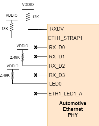
The Ethernet PHY uses many functional pins as strap option to place the device into specific modes of operation.
 Figure 2-6 Automotive Ethernet PHY
Strapping Resistors
Figure 2-6 Automotive Ethernet PHY
Strapping ResistorsTable 2-3 Recommended 3-level Strap
Resistor Ratios
| MODE | IDEAL RH (kΩ) for VDDIO = 3.3V |
|---|---|
| 1 | OPEN |
| 2 | 13 |
| 3 | 4.5 |
Table 2-4 Recommended 2-level Strap
Resistor
| MODE | IDEAL RH (kΩ) |
|---|---|
| 1 | OPEN |
| 2 | 2.49 |
Table 2-5 Industrial 1 Gbit Ethernet PHY
Strapping Resistors
| Functional Pin | Default Mode | Mode on DP83TG720-EVM-AM2 | Pull-Up | Function |
|---|---|---|---|---|
| RX_D0 | 1 | 1 | OPEN | MAC Interface: RGMII (Align mode) |
| RX_D1 | 1 | 1 | OPEN | |
| RX_D2 | 1 | 2 (2-level) | 2.49kΩ | |
| RX_CTRL | 2 (3-level) | 13kΩ | PHY address: 0xC (0b01100) | |
| STRP_1 | 2 (3-level) | 13kΩ | ||
| LED_0 | 1 | 2 (2-level) | 2.49kΩ | MS=0 |
| LED_1 | 1 | 1 | OPEN | Autonomous |