SPRUJE1 July   2024


  1.   1
  2.   Description
  3.   Get Started
  4.   Features
  5.   5
  6. 1Evaluation Module Overview
    1. 1.1 Introduction
    2. 1.2 Kit Contents
    3. 1.3 Specification
    4. 1.4 Device Information
  7. 2Hardware
    1. 2.1 Key Features
      1. 2.1.1 Microcontroller
      2. 2.1.2 Power Supply
      3. 2.1.3 JTAG and Emulator
      4. 2.1.4 Expansion Connectors/Headers to Support Application Specific Add-On Boards
      5. 2.1.5 Adapter Boards
    2. 2.2 Important Usage Notes
      1. 2.2.1 Electrostatic Discharge (ESD) Compliance
      2. 2.2.2 IO Cable Length
    3. 2.3 Functional Block Diagram
    4. 2.4 Power ON/OFF Procedures
      1. 2.4.1 Power-On Procedure
      2. 2.4.2 Power-Off Procedure
      3. 2.4.3 Power Test Points
    5. 2.5 Peripheral and Major Component Description
      1. 2.5.1 UART Interface
      2. 2.5.2 JTAG Interface
      3. 2.5.3 DAC Interface
      4. 2.5.4 USB Interface
        1. 2.5.4.1 CC Controller
      5. 2.5.5 I2C Interface
      6. 2.5.6 Power
        1. 2.5.6.1 Power Requirement
        2. 2.5.6.2 Power Input
      7. 2.5.7 XDS110 Board User Setup and Configuration
        1. 2.5.7.1 JTAG/cJTAG Switch
        2. 2.5.7.2 UART and SPI Switch
      8. 2.5.8 Expansion Headers
        1. 2.5.8.1 Emulator Connector
        2. 2.5.8.2 DAC Header
        3. 2.5.8.3 Debug Header
      9. 2.5.9 Use Cases
        1. 2.5.9.1 Case 1: Non-Isolated XDS110 and controlSOM
        2. 2.5.9.2 Case 2: Isolated XDS110, controlSOM, Baseboard
  8. 3Hardware Design Files
    1. 3.1 Schematics
    2. 3.2 Bill of Materials (BOM)
  9. 4Compliance Information
    1. 4.1 Compliance and Certifications
  10. 5Additional Information
    1. 5.1 Trademarks
  11. 6Related Documentation
    1. 6.1 Supplemental Content

UART and SPI Switch

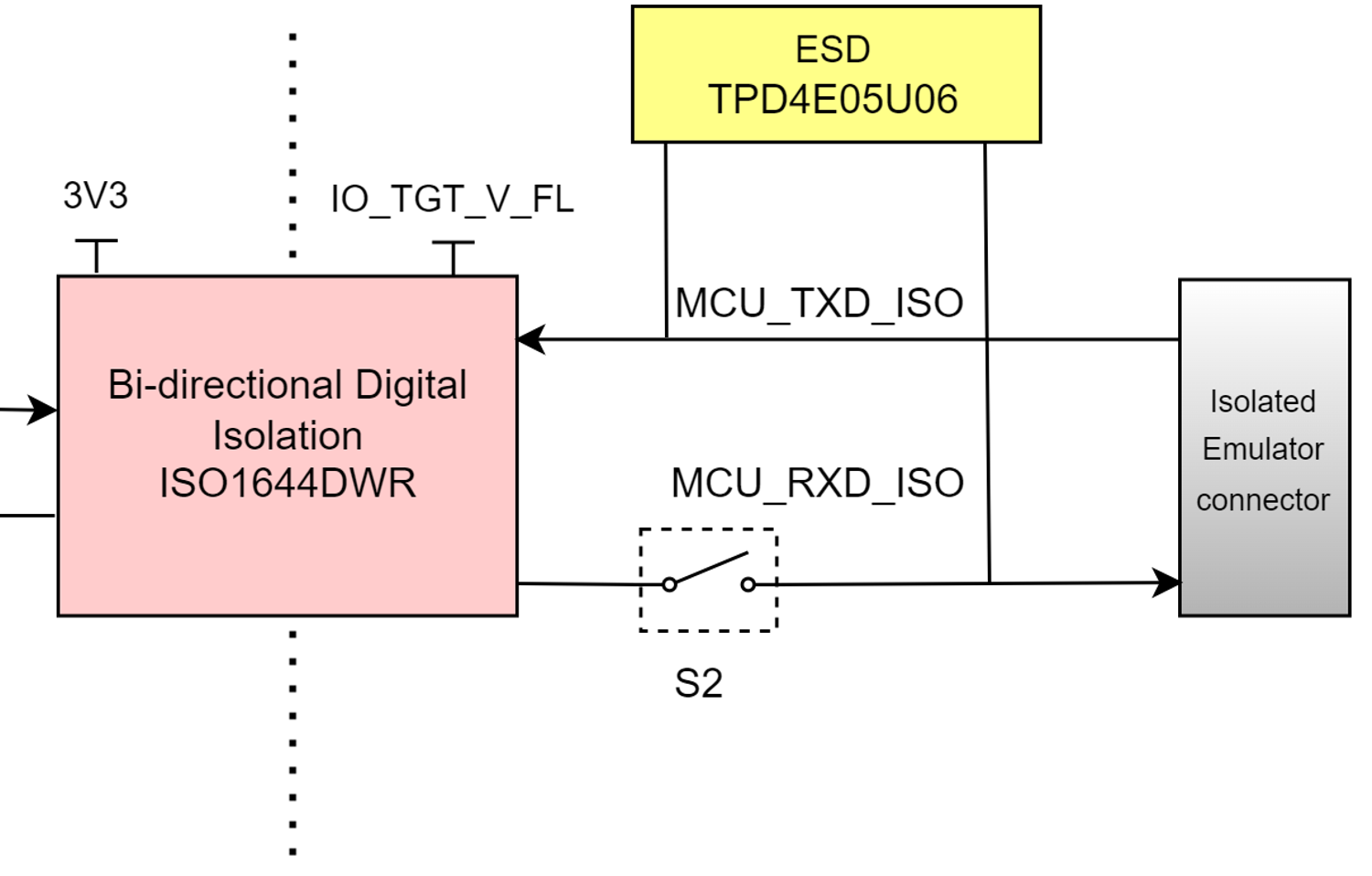
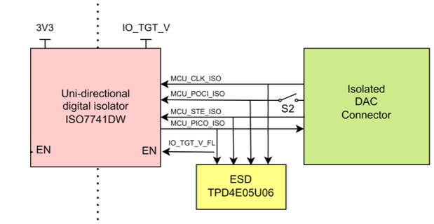
XDS110 board has one SPST, 2 position DIP Switch (S2) to set the SPI and UART signals to the emulator connector. POCI signal from digital isolator is connected to the emulator connector, when the switch (S2.1) is set to ON condition. Similarly, the receiver (Rx) signal of UART from digital isolator is connected to the emulator connector, when the switch (S2.2) is set to ON condition.

Table 2-5 UART and SPI Switch Selection
Switch State Switch Position UART and SPI Signal Selected
S2.1-S2.4 ON SPI – POCI signal
S2.2-S2.3 ON UART – RX signal
XDS110ISO-EVM UART Switch Figure 2-10 UART Switch
XDS110ISO-EVM SPI Switch Figure 2-11 SPI Switch