SPRUJF4A October 2024 – December 2024
- 1
- Description
- Features
- Applications
- 5
- 1Evaluation Module Overview
- 2Hardware
- 3Motor Control Software
-
4Test Procedure and Results
- 4.1 Build Level 1: CPU and Board Setup
- 4.2 Build Level 2: Open-Loop Check With ADC Feedback
- 4.3 Build Level 3: Closed Current Loop Check
- 4.4 Build Level 4: Full Motor Drive Control
- 4.5 Test Procedure
- 4.6 Performance Data and Results
- 5Hardware Design Files
- 6Additional Information
- 7References
- 8Revision History
2.1.4.2 Single-Shunt Current Sensing
The single-shunt current-sensing technique measures the DC-link bus current, with knowledge of the power FET switching states and reconstructs the three-phase current of the motor. The detailed description of the single shunt technique is described in the Sensorless-FOC for PMSM With Single DC-Link Shunt application note.
On this reference board, implement the single-shunt current-sensing technique by removing two shunts and shorting the connection of the U, V, W ground of the power module as shown in Figure 2-8.
 Figure 2-8 Single-Shunt Current-Sensing
Resistor Configuration
Figure 2-8 Single-Shunt Current-Sensing
Resistor Configuration- On the motherboard, remove current shunt resistors R81, and R82, just keep only shunt resistor R80 to sense the DC-Link current.
- On the TMS320F2800137 daughterboard, remove C23 to increase U3A bandwidth for single-shunt sampling.
- Use a thick wire to connect the NU, NV, and NW pins together.
 Figure 2-9 Single-Shunt Current-Sensing Circuit for TMS320F2800137
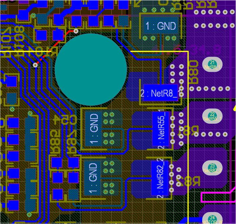
By default, the board has three shunt resistors. Figure 2-10 shows the layout of the shunt resistors. To implement single-shunt resistor sensing, remove R81 and R82 while keeping R80. Solder NU, NV and NW (pin 2 of R80, R81, and R82) together. All three phase currents now flow through only R80.
 Figure 2-10 Shunt Resistors Layout
The DC-Link current is a unidirectional signal, so the DC current offset can be set to a minimum or maximum value to improve the ADC sampling range for the DC-Link current as Figure 2-11 shows. On the TMS320F2800137 daughterboard, change R23 from 10 kΩ to 1 kΩ/1% resistor for the reference voltage to have 0.3-V offset for DC current sensing.
 Figure 2-11 DC Offset Reference for Single Shunt of TMS320F2800137 Daughterboard
The transfer function of this current sampling circuit and the calculation for single shunt are the same as for three shunt.