SPRUJG2 December   2024 AM62D-Q1


  1.   1
  2.   Description
  3.   Get Started
  4.   Features
  5.   5
  6. 1Evaluation Module Overview
    1. 1.1 Introduction
    2. 1.2 Kit Contents
    3. 1.3 Specification
    4. 1.4 Device Information
    5. 1.5 EVM Revisions and Assembly Variants
  7. 2Hardware
    1. 2.1  Additional Images
    2. 2.2  Key Features
      1. 2.2.1 Processor
      2. 2.2.2 Power Supply
      3. 2.2.3 Memory
      4. 2.2.4 JTAG/Emulator
      5. 2.2.5 Supported Interfaces and Peripherals
      6. 2.2.6 Expansion Connectors/Headers to Support Application Specific Add‐On Boards
    3. 2.3  Power Requirement
    4. 2.4  Setup and Configuration
      1. 2.4.1 EVM DIP Switches
      2. 2.4.2 Boot modes
      3. 2.4.3 User Test LEDs
    5. 2.5  Power ON/OFF Procedures
      1. 2.5.1 Power ON Procedure
      2. 2.5.2 Power OFF Procedure
      3. 2.5.3 Power Test Points
    6. 2.6  Interfaces
      1. 2.6.1  AM62D Audio EVM Interface Mapping
      2. 2.6.2  Audio Interface
        1. 2.6.2.1 Audio Stereo Lineouts
        2. 2.6.2.2 Audio Microphone / Line In
      3. 2.6.3  JTAG Interface
      4. 2.6.4  UART Interface
      5. 2.6.5  USB Interface
        1. 2.6.5.1 USB2.0 Type-A Interface
        2. 2.6.5.2 USB2.0 Type-C Interface
      6. 2.6.6  MCAN Interface
      7. 2.6.7  Memory Interfaces
        1. 2.6.7.1 LPDDR4 Interface
        2. 2.6.7.2 Octal Serial Peripheral Interface (OSPI)
        3. 2.6.7.3 MMC Interfaces
          1. 2.6.7.3.1 MMC0 - eMMC Interface
          2. 2.6.7.3.2 MMC1 - MicroSD Interface
        4. 2.6.7.4 Board ID EEPROM
      8. 2.6.8  Ethernet Interface
      9. 2.6.9  CPSW Ethernet 1 and CPSW Ethernet 2
      10. 2.6.10 GPIO Port Expander
      11. 2.6.11 GPIO Mapping
    7. 2.7  Power
      1. 2.7.1 Power Input
      2. 2.7.2 Power Supply
      3. 2.7.3 Power Sequencing
      4. 2.7.4 AM62D SOC Power
      5. 2.7.5 Current Monitoring
    8. 2.8  Clocking
      1. 2.8.1 Peripheral Ref Clock
    9. 2.9  Reset
    10. 2.10 CPLD Mapping
    11. 2.11 Audio Expansion Connectors (Headers)
      1. 2.11.1 Audio Expansion Connector 1
      2. 2.11.2 Audio Expansion Connector 2
    12. 2.12 Interrupt
    13. 2.13 I2C Address Mapping
  8. 3Hardware Design Files
  9. 4Compliance Information
    1. 4.1 Compliance and Certifications
  10. 5Additional Information
    1. 5.1 Known Hardware or Software Issues
    2. 5.2 Trademarks

MCAN Interface

The AM62D Audio EVM is equipped with a dual MCAN Transceivers manufacturer part number TCAN3413DR that is connected to the MCAN0 and MCU_MCAN0 interface of the AM62D SoC. The MCAN Transceiver has two power inputs, VIO is the transceiver 1.8V system level shifting supply voltage and VCC is the transceiver 3.3V supply voltage. The SoC CAN data transmit data input is mapped to TXD of the transceiver and the CAN receive data output of the transceiver is mapped to the RXD of the SoC.
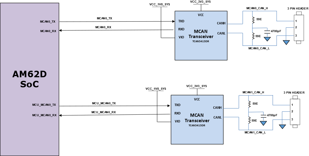
AUDIO-AM62D-EVM MCAN Block Diagram Figure 2-11 MCAN Block Diagram

The system has a 120Ω split termination on the CANH and CANL signals to improve EMI performance. Split termination improves the electromagnetic emissions behavior of the network by eliminating fluctuations in the bus common-mode voltages at the start and end of message transmissions.

The low-level and high-level CAN bus input output lines are terminated to a three-pin header.