SPRUJG2 December   2024 AM62D-Q1


  1.   1
  2.   Description
  3.   Get Started
  4.   Features
  5.   5
  6. 1Evaluation Module Overview
    1. 1.1 Introduction
    2. 1.2 Kit Contents
    3. 1.3 Specification
    4. 1.4 Device Information
    5. 1.5 EVM Revisions and Assembly Variants
  7. 2Hardware
    1. 2.1  Additional Images
    2. 2.2  Key Features
      1. 2.2.1 Processor
      2. 2.2.2 Power Supply
      3. 2.2.3 Memory
      4. 2.2.4 JTAG/Emulator
      5. 2.2.5 Supported Interfaces and Peripherals
      6. 2.2.6 Expansion Connectors/Headers to Support Application Specific Add‐On Boards
    3. 2.3  Power Requirement
    4. 2.4  Setup and Configuration
      1. 2.4.1 EVM DIP Switches
      2. 2.4.2 Boot modes
      3. 2.4.3 User Test LEDs
    5. 2.5  Power ON/OFF Procedures
      1. 2.5.1 Power ON Procedure
      2. 2.5.2 Power OFF Procedure
      3. 2.5.3 Power Test Points
    6. 2.6  Interfaces
      1. 2.6.1  AM62D Audio EVM Interface Mapping
      2. 2.6.2  Audio Interface
        1. 2.6.2.1 Audio Stereo Lineouts
        2. 2.6.2.2 Audio Microphone / Line In
      3. 2.6.3  JTAG Interface
      4. 2.6.4  UART Interface
      5. 2.6.5  USB Interface
        1. 2.6.5.1 USB2.0 Type-A Interface
        2. 2.6.5.2 USB2.0 Type-C Interface
      6. 2.6.6  MCAN Interface
      7. 2.6.7  Memory Interfaces
        1. 2.6.7.1 LPDDR4 Interface
        2. 2.6.7.2 Octal Serial Peripheral Interface (OSPI)
        3. 2.6.7.3 MMC Interfaces
          1. 2.6.7.3.1 MMC0 - eMMC Interface
          2. 2.6.7.3.2 MMC1 - MicroSD Interface
        4. 2.6.7.4 Board ID EEPROM
      8. 2.6.8  Ethernet Interface
      9. 2.6.9  CPSW Ethernet 1 and CPSW Ethernet 2
      10. 2.6.10 GPIO Port Expander
      11. 2.6.11 GPIO Mapping
    7. 2.7  Power
      1. 2.7.1 Power Input
      2. 2.7.2 Power Supply
      3. 2.7.3 Power Sequencing
      4. 2.7.4 AM62D SOC Power
      5. 2.7.5 Current Monitoring
    8. 2.8  Clocking
      1. 2.8.1 Peripheral Ref Clock
    9. 2.9  Reset
    10. 2.10 CPLD Mapping
    11. 2.11 Audio Expansion Connectors (Headers)
      1. 2.11.1 Audio Expansion Connector 1
      2. 2.11.2 Audio Expansion Connector 2
    12. 2.12 Interrupt
    13. 2.13 I2C Address Mapping
  8. 3Hardware Design Files
  9. 4Compliance Information
    1. 4.1 Compliance and Certifications
  10. 5Additional Information
    1. 5.1 Known Hardware or Software Issues
    2. 5.2 Trademarks

Audio Microphone / Line In

The AM62D Audio EVM will have audio analog-to-digital converters (ADC) manufacturer part number PCM6240QRTVRQ1 to interface with McASP2 of SoC. The PCM6240 has Analog supply of 3.3V and digital supply of 1.8V and VBAT_IN is used for enabling input fault diagnostics.

The PCM6240QRTVRQ1 configuration control is supported over the SoC_I2C0 instance. In PCM6240QRTVRQ1 I2C target address is set using ADDR1_MISO and ADDR0_SCLK pins. The I2C address for audio device (PCM6240) are 0x48 and 0x49. The Buffer enable manufacturer part number SN74LVC1G126DBVR for the serial data output is controlled by the CPLD1.

The ADC is connected to 2x stacked 3.5mm TRS Audio Jack connectors with manufacturer part number STX-4235 for 4x Stereo Audio Jack Mic/Line In.

Reset: The reset for the PCM6240 is connected to a circuit that ANDs the RESETSTATz from the AM62D SoC with the signal GPIO_PCM_RST from the I/O expander. A pull-up resistor is provided on PCM_RSTn to set the default active state.
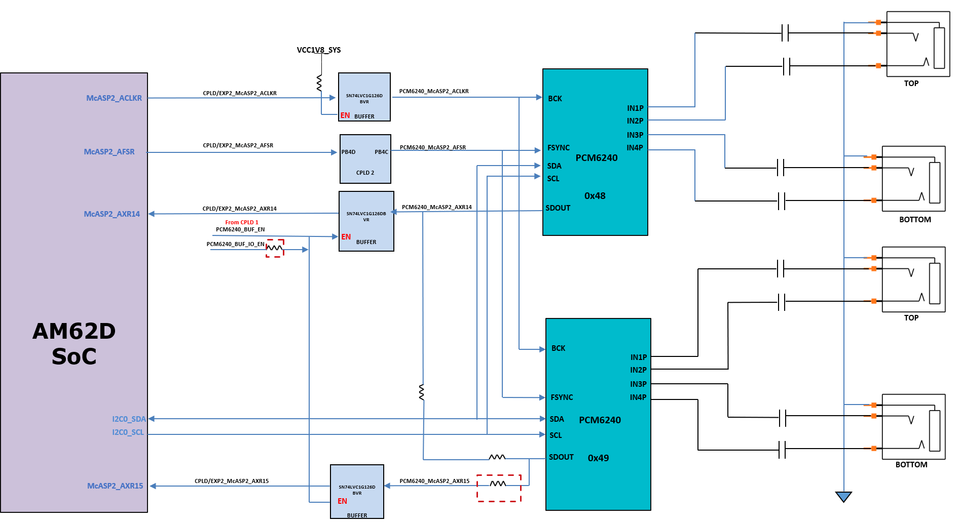
AUDIO-AM62D-EVM Audio Microphone / Line In
                    Block Diagram Figure 2-6 Audio Microphone / Line In Block Diagram