SPRUJG2 December 2024 AM62D-Q1
- 1
- Description
- Get Started
- Features
- 5
- 1Evaluation Module Overview
-
2Hardware
- 2.1 Additional Images
- 2.2 Key Features
- 2.3 Power Requirement
- 2.4 Setup and Configuration
- 2.5 Power ON/OFF Procedures
- 2.6 Interfaces
- 2.7 Power
- 2.8 Clocking
- 2.9 Reset
- 2.10 CPLD Mapping
- 2.11 Audio Expansion Connectors (Headers)
- 2.12 Interrupt
- 2.13 I2C Address Mapping
- 3Hardware Design Files
- 4Compliance Information
- 5Additional Information
2.7.2 Power Supply
The AM62D Audio EVM utilizes an array of DC-DC converters to supply the various memories, clocks, SoC and other components on the board with the necessary voltage and the power required.
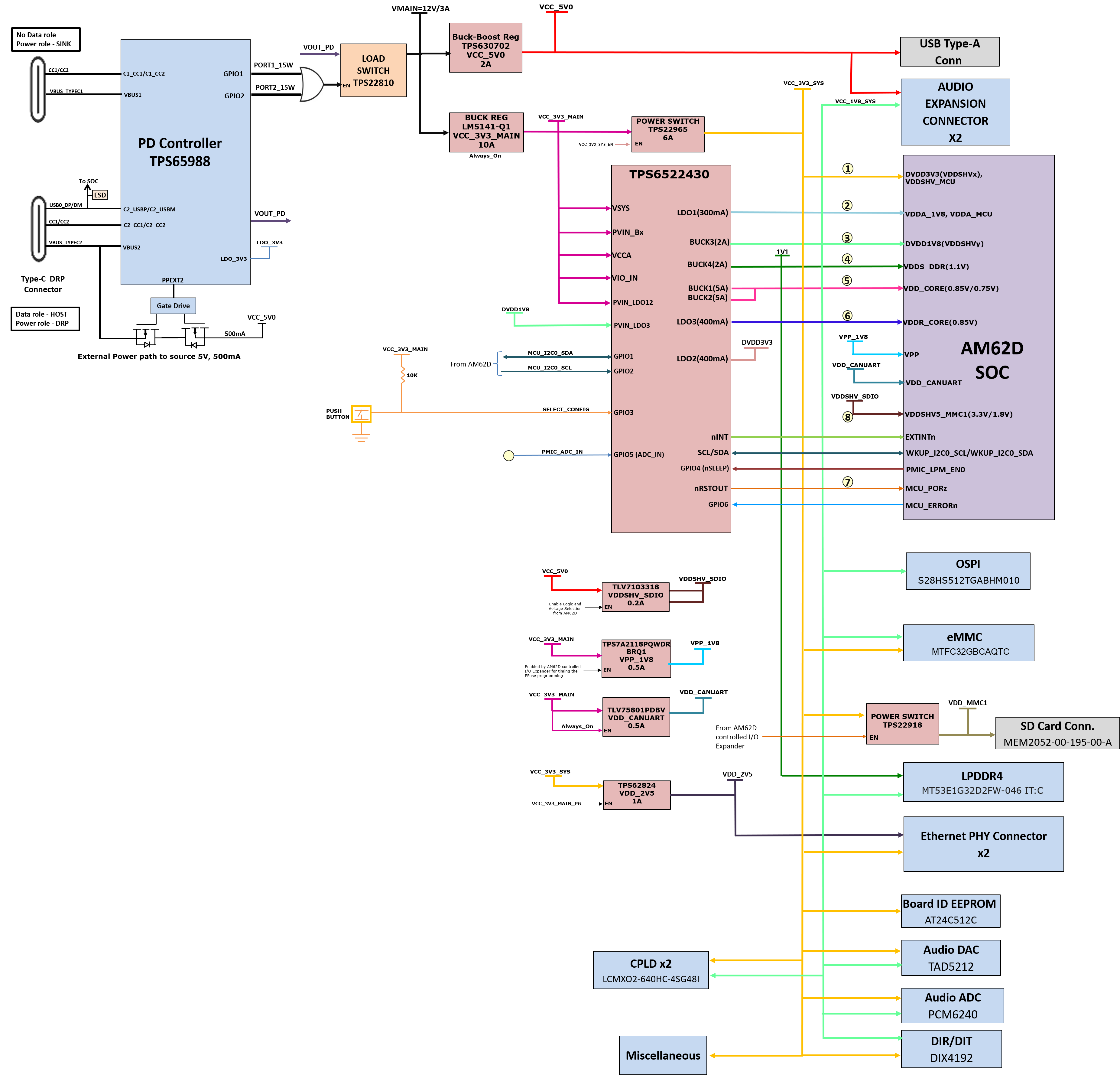
Figure 2-19 shows the various discrete regulators, PMIC and LDOs used to generate power rails and the current consumption of each peripheral on the AM62D Audio EVM board.
 Figure 2-19 Power Architecture
The following sections describe the power distribution network topology that supplies the EVM board, supporting components and reference voltages.
The AM62D Audio EVM board includes a power solution based on discrete power supply components. The initial stage of the power supply will be VBUS voltage from either of the two USB Type-C connectors J24 and J25. USB Type-C Dual PD controller of manufacturer part number TPS65988DHRSHR is used for negotiation of the required power to the system. The GPIO1 and GPIO2 of the PD are used for negotiation if the power is ≥ 15W.This logic enables the load switch for VMAIN supply .
Buck-Boost controller TPS630702RNMR and Buck converter LM5141-Q1 are used for the generation of 5V and 3.3V respectively and the input to the regulators is the PD output. These 3.3V and 5V are the primary voltages for the AM62D Audio EVM Board power resources. The 3.3V supply generated from the Buck regulator LM5141-Q1 is the input supply to the PMIC, various SOC regulators and LDOs. The 5V supply generated from the Buck Boost regulator TPS630702RNMR is used for powering the on-board peripherals. Discrete regulators and LDOs used on Board are:
- TPS62824DMQR – To generate VDD_2V5 rail for PHY and DDR peripherals
- PTPS6522430RAHRQ1 (PMIC) – To generate various SoC and Peripheral supplies
- TLV75801PDBVT LDO – VDD_CANUART power of SoC
- TPS7A2118PQWDRBRQ1 – To generate VPP_1V8 for SoC
- TPS79601 LDO - XDS110 On board emulator
- TPS73533 LDO - FT4232 USB-to-UART Bridge