SSZT121 november 2021 TPS61022 , TPS61094 , TPS63802
Other Parts Discussed in Post: TPS61094 TPS61022 TPS63802
| Watch the TPS61094 in action | |

|
See how the TPS61094 boost converter integrates a buck mode for supercapacitor charging while maintaining ultra-low IQ in our video "Achieve ultra-low 60-nA IQ with the TPS61094." |
Effective Ways to Implement Backup Power from Supercapacitors
Many modern, smart Internet-of-things (IoT) devices that run from line power need backup power to safely power down or to perform last-gasp communication in the event of an unexpected power outage. For example, an electricity meter could share details about the time, location and duration of a power outage through a radio-frequency (RF) interface. Recently, narrowband IoT (NB-IoT) has become popular for such actions given these advantages:
- The use of existing 2G, 3G and 4G bands.
- Support from one or more operators in the Americas and European and Asian countries.
- Significantly lower power and peak currents compared to general packet radio service (GPRS).
A well-designed backup power scheme helps deliver the right amount of backup power, switches seamlessly between normal and backup operation, and can support many power outages without maintenance. In this article, we’ll present a simple method to implement a backup power scheme for NB-IoT and RF standards using TI’s TPS61094 buck/boost converter and a single supercapacitor. We’ll also compare the TPS61094-based solution with existing TI reference designs.
Backup Power for NB-IoT
Table 1 shows the current consumption during different NB-IoT operating modes over time. Peaking at 310 mA in data transmit mode for 1.32 s, the load varies significantly with operation mode changes. The average current consumption in the entire process is 30 mA for 80 s – a load duration that requires enough backup power and seamless power switching when the main power grid is suddenly down. The TPS61094 60-nA quiescent current (IQ) bidirectional buck/boost converter enables reliable and simple backup power designs, while serving as a one-chip solution that achieves supercapacitor charge and discharge without extra circuitry.
| Mode | Sleep Mode | Transmit mode | Transmit Mode | ||||||
|---|---|---|---|---|---|---|---|---|---|
| Wake-up & scan | Data Tx | RRC activity | RRC release | PSM | |||||
| Current (mA) | 0.003 | 28 | 310 | 40 | 20 | 310 | 20 | 8 | 30 (average) |
| Time (s)(1) | 2 | 1.32 | 12.68 | 30 | 1.25 | 1 | 30 | 80 (total time) | |
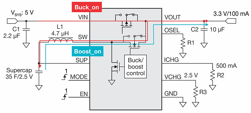
To implement an effective backup power circuit with a single supercapacitor and the TPS61094, Figure 1 shows how we configured the TPS61094 evaluation module (EVM) to support enough backup power for the NB-IoT load profile in Table 1.
 Figure 1 TPS61094 EVM Backup Power
Configuration
Figure 1 TPS61094 EVM Backup Power
ConfigurationWhen system power is on, the TPS61094 enters Buck_on mode, which turns on the bypass field-effect transistor (FET), supplies the supercapacitor with 500 mA of constant current, and stops charging when the voltage across the supercapacitor is 2.5 V. VSYS powers VOUT directly. When a power outage causes VSYS to drop, the TPS61094 automatically enters Boost_on mode, turning off the bypass FET and supplying VOUT from the energy stored in the supercapacitor.
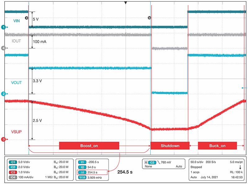
Figure 2 shows oscilloscope measurements for a complete backup power cycle. VIN represents the system voltage from the grid. VOUT is the output voltage from the TPS61094 and VSUP is the supercapacitor voltage. IOUT shows the load current consumption. In our example, the load is 100 mA, which is 3.33 times the average current consumption of the load profile. We increased the load in order to determine how the TPS61094 switches input power when the grid is down in a more extreme load condition.
When system power goes down suddenly, the TPS61094 immediately enters Boost_on mode and regulates VOUT using power from the supercapacitor. The buck/boost converter supplies the required output current for 254.5 s, which equals 11.5 NB-IoT transactions. The TPS61094 discharges the supercapacitor until its voltage drops to 0.7 V; at that point, the device enters shutdown mode until the system VIN returns. In Buck_on mode, the TPS61094 seamlessly charges the supercapacitor with constant current. As you can see in Figure 2, the switchover between supercapacitor discharge and charge is very smooth.
 Figure 2 TPS61094 Power-cycle
Measurements
Figure 2 TPS61094 Power-cycle
MeasurementsOther Backup Power Implementations
There are also other solutions available to you, each with advantages and drawbacks. The Supercapacitor Backup Power Supply for E-Meters Reference Design, uses discrete circuitry to charge the supercapacitor and the TPS61022 boost converter to boost the supercapacitor voltage to a higher system voltage when the grid is down. The TPS61022 output current capability is higher than it is for the TPS61094 solution, but will require more external components.
Another approach is the Supercapacitor Backup Power Supply with Current Limit and Active Cell Balancing Reference Design, which uses the TPS63802 buck-boost converter as a supercapacitor charger and voltage regulator and eliminates extra discrete charging circuitry. It still needs additional external components to achieve power ORing, charge current limit and supercapacitor terminal voltage settings, however.
Table 2 lists the most important characteristics of each backup power approach.
| Solution | TPS61094 | 1S boost design | 2S buck-boost design |
|---|---|---|---|
| Core device | TPS61094 | TPS61022 | TPS63802 |
| Device IQ (uA) | 0.06 | 27 | 11 |
| Integrity | High | Low | Medium |
| Charge circuitry | Integrated | Discrete | Partly integrated |
| Supercapacitor configuration | 1S | 1S | 2S |
| Average maximum output current (mA) for 3.3 VOUT (1) | 300 | 650 | 1,300 |
| ORing circuitry | Integrated | Discrete | Discrete |
| Programmable supercapacitor terminal voltage | Integrated | Discrete | Discrete |
| Programmable charge current | Integrated | Discrete | Discrete |
| Programmable output voltage | Integrated | Integrated | Integrated |
| VIN range (V) | 0.7-5.5 | 10-12 | 3.3-5 |
| VOUT range (V) | 2.7-5.4 | 2.2-5.5 | 1.8 to 4.9 V |
| Key components for backup power | TPS61094 | Discrete charger, TPS61022 | TPS63802, LM6100, INA181A, operational amplifier |
Conclusion
Low-power, wireless standards are becoming increasingly popular. For high-integration, simple design and the best light-load efficiency, the TPS61094 is a good choice for backup power applications with LTE-M, Lora, Bluetooth and other emerging wireless interfaces.
If you need more output current, the e-meter or current limit reference designs are very effective solutions. Although they require more discrete components, they can support higher-power RF transmissions such as GPRS.
Additional Resources
- Download the TPS61094 data sheet.
- Check out the TPS63802 hardware development kit.
- See the application brief, “Solving the Backup Power Supply Challenge for Electricity Meters with High-Power Wireless Communications.”
- Read the Analog Design Journal article, “IQ: What It Is, What It Isn’t, and How to Use It.”