SSZT164 may 2021
A Hall-effect sensor, also known as a Hall sensor, monitors magnetic fields with high accuracy, consistency and reliability. Why is that important? Because it enables you to sense the position and movement of objects in a system. In this article, I’ll explain what a Hall-effect sensor is, its basic building blocks and functionality, and common use cases for Hall-effect sensing products.
A Hall-effect sensor is not your typical integrated circuit (IC), because unlike most ICs, it indirectly interacts with its key “circuit” – a magnet! As shown in Figure 1, the elementary Hall-effect sensor comprises a Hall element, which turns a magnetic field into a voltage, and processing circuitry such as an operational amplifier. Both analog and digital processing circuitry are critical to a Hall-effect sensor’s operation because the output voltage from a Hall element is tiny – sometimes in the microvolt range. One of the simplest Hall-effect sensors uses only three-pin packages, small-outline transistor (SOT)-23 or transistor outline (TO)-92, for the power supply, ground connection and output.
 Figure 1 A Basic Hall-effect
Sensor
Figure 1 A Basic Hall-effect
SensorMagnetic fields are never straight lines, as they extend from one pole to the other, but Figure 1 shows straight lines impinging on the sensor for simplicity. Knowing exactly how these field vectors behave in space allows you to do many creative things with them. Check out the application notes on TI’s Magnetic Sensors Support and Training page for some basic ideas.
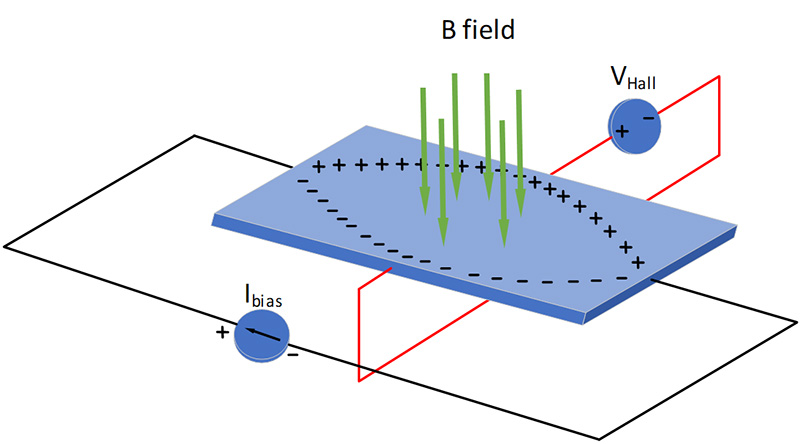
Ever thought about how Hall-effect sensors work? The simple answer is that a small voltage develops across a piece of conductive material, crowding electrons to one side as current is forced through the conductor and a magnetic field is applied in an orthogonal direction (see Figure 2). This voltage potential is attributed to the Lorentz force, discovered by Edwin Hall in 1879.
 Figure 2 The Hall Effect
Notice the magnetic field direction relative to the Hall element? That is a key aspect of the Hall-effect sensor that you need to consider in your mechanical design. Most Hall-effect sensor data sheets specify the expected direction of the magnetic field relative to the package surface. TI has multiple options available in its Hall-effect sensor portfolio.
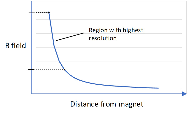
This foundational understanding of how Hall-effect sensors function is necessary so that you know how to use them effectively, with proper position relative to a magnet. But you also need to know how the magnetic fields produced by a magnet behave with distance. Figure 3 shows a simple graph of how a magnetic field decays over distance from the magnet.
 Figure 3 Magnetic Field Decay over
Distance
Figure 3 Magnetic Field Decay over
DistanceTo maximize the measurement resolution, you will need to ensure that the system’s minimum-to-maximum distance values are within the region with the greatest change in magnetic field.
There are three types of position Hall-effect sensors available today:
- A Hall-effect switch is a digital output device that switches states based on the magnetic field it senses. As the magnet draws closer to the sensor, the magnetic field it senses becomes stronger and will switch into an active state called the BOP. As the magnetic field it senses weakens (as the magnet pulls farther away), the device switches back to its inactive state at a threshold called BRP.
- A Hall-effect latch is almost identical in operation to a switch, except that it has a BRP point that is opposite in magnetic polarity. In other words, it requires an alternating magnetic field polarity to switch its output voltage state.
- A Hall-effect linear sensor, also known as a linear, is an analog device that varies its output voltage proportional to the magnetic field it is sensing. With no magnetic field present, the device will produce an output voltage equal to half the power-supply voltage (VQ). As the magnetic field strengthens, the output voltage will either start pulling it closer to ground (magnetic north) or closer to the power-supply voltage (magnetic south) until it reaches a saturation point. The sensor will not measure magnetic fields stronger than those reached at saturation because of the unchanging voltage output. Switches and linear devices come in unipolar versions (that can only sense north or south fields) or omnipolar switches and bipolar linears (that sense both north and south fields).
Figure 4 shows the respective transfer functions of the three Hall-effect sensor types.
 Figure 4 Switch, Latch and Linear
Sensor Transfer Functions
Figure 4 Switch, Latch and Linear
Sensor Transfer FunctionsThe magnetic points BOP and BRP in switches and latches define the hysteresis value (BHYS = BOP - BRP). Leveraging hysteresis in your system will prevent bouncing back and forth between output states.
Common Hall-effect Sensor Applications
Switches are common in laptops, refrigerator doors and end-of-line switches to detect when a magnet comes in close proximity to the sensor. Latches are popular in rotary encoding and motor commutation applications, where the rotational aspect of the application is ripe for continuously monitoring the position of the rotating shaft. Linear sensors can accurately measure the displacement of an object, so they are suitable for linear actuators, variable speed triggers and acceleration pedals.
Hall-effect sensors provide a cost-effective way to monitor moving objects. Depending on the application, you can use a switch, latch or linear sensor. If you’d like to continue learning about Hall-effect sensors, I encourage you to check out our TI Precision Labs training series on magnetic sensors.
Additional Resources
- Read the application report, “Understanding & Applying Hall Effect Sensor Datasheets” to learn more about how to make better use of the data in a Hall-effect sensor data sheet.
- Read the application report, “Designing Single and Multiple Position Switches Using TI Hall Effect Sensors.”
- Check out these foundational linear sensor application reports, “Linear Hall Effect Sensor Angle Measurement Theory, Implementation, and Calibration” and “Linear Hall Effect Sensor Array Design.”