SSZT216 December   2020 TPS23730


  1.   1
  2.   2
    1.     3
    2.     ACF topology
    3.     Synchronous flyback topology
    4.     Nonsynchronous flyback topology
    5.     Additional resources

Brett Colteaux

GUID-2E66BD74-0588-4B5F-8AF0-9CF03524FE46-low.jpg

Designers have several topologies to choose from when designing 51-W isolated DC/DC power over Ethernet (PoE) systems. In a perfect world, each topology would cost nothing, have 100% efficiency and be smaller than a grain of sand. But since that isn’t possible, system designers are forced to choose the topology that closest meets their needs. In this article, I’ll discuss three of the most commonly used 51-W power topologies for isolated DC/DC PoE subsystems – active clamp forward (ACF), synchronous flyback and nonsynchronous flyback – and the trade-offs of each.

ACF topology
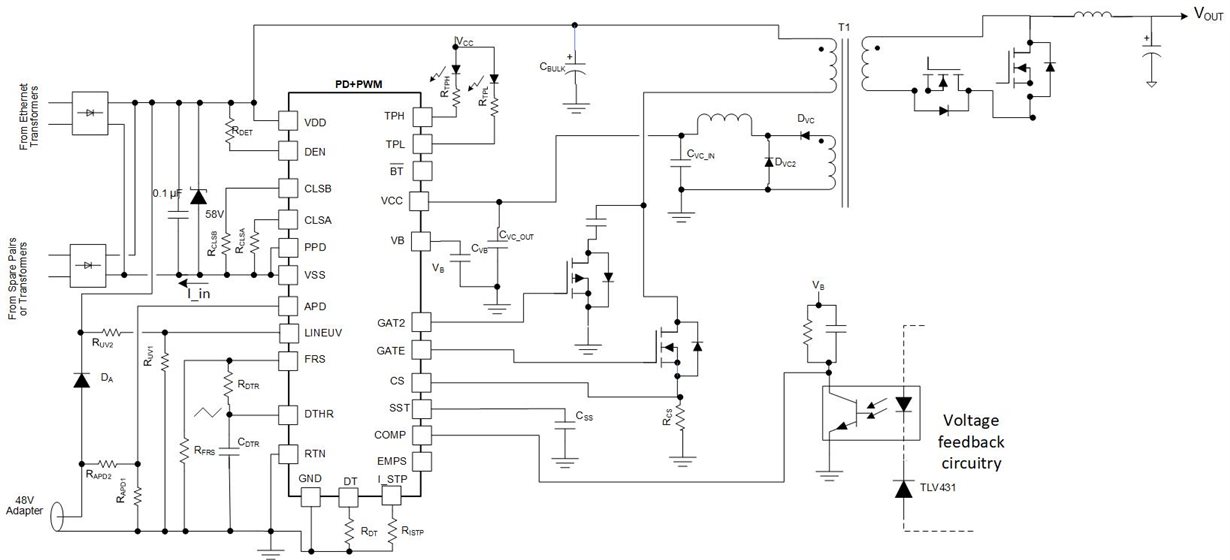
The ACF topology enables the highest efficiency. This advantage is important when maximizing the power available to the load, especially when bumping up against class or type power-level limits in PoE systems. End equipment with small form factors or enclosures tends to have ACF topologies to reduce heat and avoid the need for a fan. ACF requires the most components, however; it’s also the most expensive and takes up the most space compared to the two other topologies. Figure 1 is an schematic from the Type 3 IEEE 802.3bt-Ready Active Clamp Forward Converter PoE Powered Device Reference Design.

GUID-CBED429C-A05A-41DD-B427-2A608B3858FE-low.jpg Figure 1 ACF topology schematic

Synchronous flyback topology

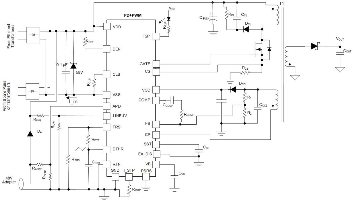
Synchronous flybacks only require two metal-oxide semiconductor field-effect transistors (MOSFETs) (instead of the four required by the ACF topology), which leads to reduced cost and size, comparatively. In addition, it is possible to reduce the number of components and board space further through primary-side regulation (PSR). PSR eliminates the need for the optocoupler and feedback circuitry, which helps cut down the cost and size of the PoE design. Both PSR and non-PSR synchronous flybacks cost less than ACF, but typically reduce efficiency by approximately 2% to 3% compared to ACF. Figure 2 illustrates a synchronous flyback topology.

GUID-2090E058-4ED4-4C74-AE33-9229C17CA46D-low.jpg Figure 2 Synchronous flyback topology schematic with PSR

Nonsynchronous flyback topology

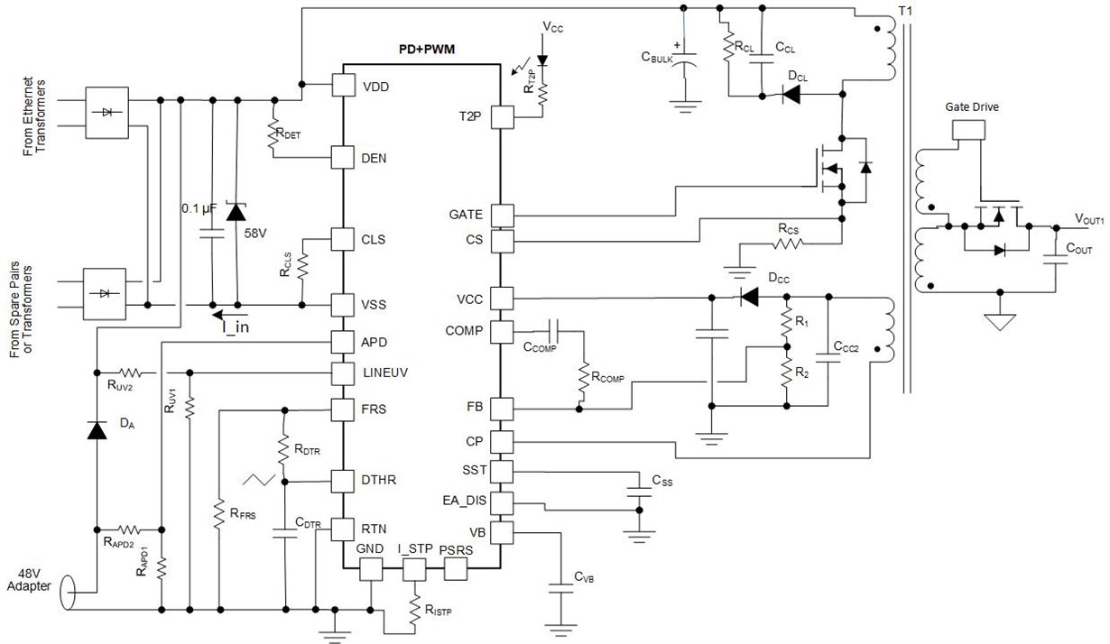
Nonsynchronous flyback topologies are the least expensive and have the lowest efficiency of the three topologies. The main difference between the synchronous and the nonsynchronous flyback is that the synchronous flyback uses a FET on the output, whereas the nonsynchronous uses a diode on the output. Since diodes are less efficient than FETs, the nonsynchronous flyback will be 1% to 2% less efficient than the synchronous flyback – but will be less costly. Figure 3 shows an example of this topology.

GUID-183AF7DF-FCC7-4BD9-A22C-B1585C89B9D6-low.jpg Figure 3 Nonsynchronous flyback topology schematic with PSR

The TPS23730 works in all three topologies. Given its system-level flexibility, the TPS23730 is recommended for any Type 3, <51-W isolated PoE design. When choosing a PoE PD for your next design, consider using TI’s PoE PD selection flowchart (Figure 4) as part of your decision-making process.
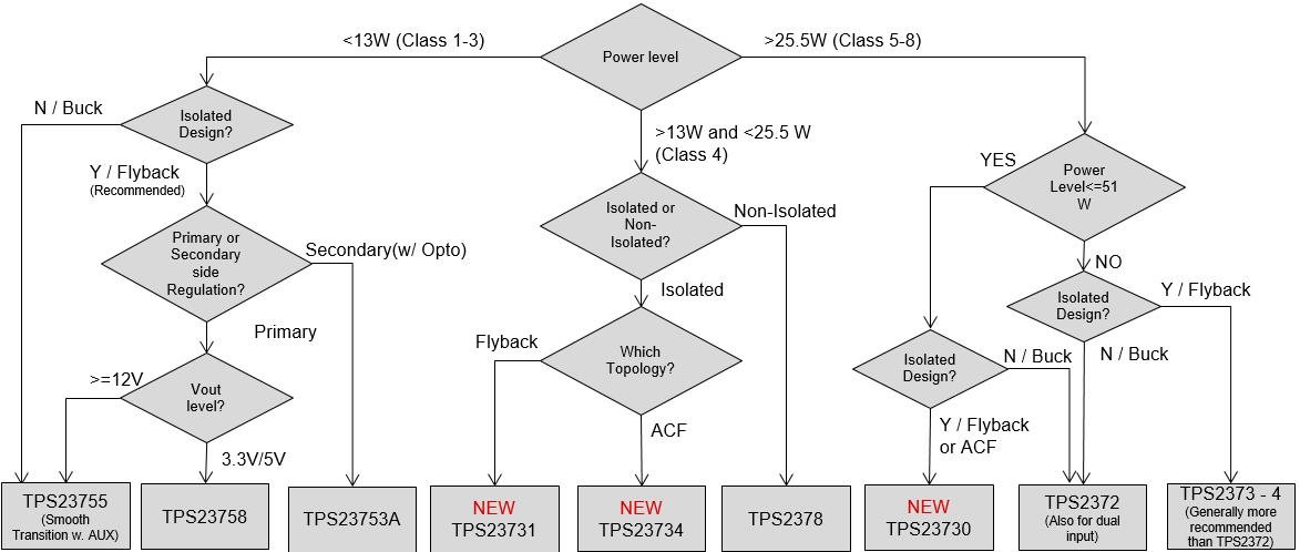
GUID-6C156B00-4F19-420A-8BD0-8A1F4777C9AE-low.jpg Figure 4 TI’s PoE PD selection flowchart

Isolated 51-W PoE designs have several common topologies. Each topology has its advantages and disadvantages, and the topology that you ultimately choose will depend on your individual priorities.