-
How an Automotive ADC Can Help Designers Achieve Functional Safety in ADAS SSZT296 june 2020 ADS7038-Q1 , ADS7138-Q1 , ADS7142-Q1
-
How an Automotive ADC Can Help Designers Achieve Functional Safety in ADAS
How an Automotive ADC Can Help Designers Achieve Functional Safety in ADAS
Krunal Maniar
Although today’s vehicles automate several aspects of the driving experience, the true forces behind moving from partially autonomous to fully autonomous cars are not car manufacturers but rather mobility service providers such as taxi companies, rental car companies, delivery service companies and cities that need to provide safe, efficient, accessible and affordable public and private transportation.
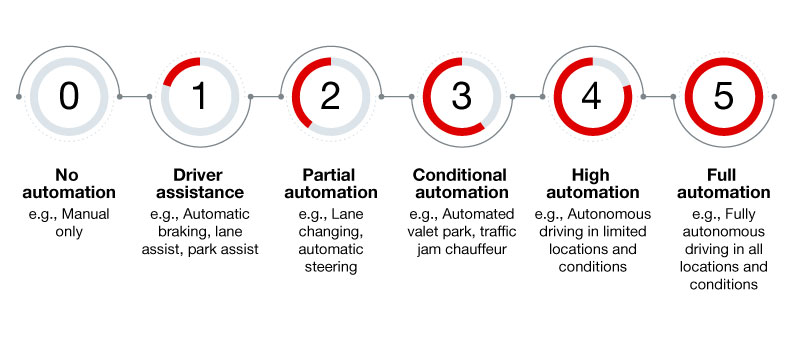
Before a fully autonomous self-driving car hits public roadways, it must progress through six different levels of automation, ranging from Level 0 (no automation) to Level 5 (full automation), as shown in Figure 1. Every jump in automation level requires substantial advanced driver assistance system (ADAS) technology advancements and proper management of all safety-critical functions.
 Figure 1 Levels of autonomous
driving
Figure 1 Levels of autonomous
drivingAutonomous vehicles use multiple sensor technologies including camera, radar and LIDAR. These sensors have their pros and cons based on different environmental conditions and distances. A sensor fusion box analyzes these sensor signals, along with data from GPS and vehicle-to-everything systems, to create an accurate three-dimensional mapping of the environment and send the appropriate action signals. Figure 2 is a block diagram of such an autonomous system.
 Figure 2 Autonomous driving
system
Figure 2 Autonomous driving
systemAs vehicles move toward higher and higher automation levels, the hardware and software subsystems become increasingly complex, and the functional safety of these subsystems becomes critical in order to avoid dangerous situations for drivers, passengers and pedestrians. These subsystems need to meet the highest levels of functional safety standards, since any malfunction can be fatal. Depending on the level of automation, as per ISO 26262, Automotive Safety Integrity Level (ASIL) grades as high as ASIL-D for the functional safety of road vehicles are required.
To achieve high levels of ASIL functional safety requirements, these subsystems need to considerably lower failure rates and improve fault coverage through the use of appropriate diagnostic monitoring mechanisms and redundant circuits in parallel. They need to measure and identify potential failures associated with different power-supply rails, detecting any abnormality in voltage or current consumption of the different power supplies as well as any fluctuations in system temperature. These failures need to be diagnosed and appropriate actions taken in timely manner. Figure 3 shows a conceptual block diagram to realize this functionality.
 Figure 3 A supply-rail and
temperature-diagnostic monitoring system
Figure 3 A supply-rail and
temperature-diagnostic monitoring systemA simpler approach using a stand-alone analog-to-digital converter (ADC) for diagnostic monitoring is becoming increasing popular. The functional safety goals can differ based on safety criticality and implementation. Also, the number of channels per project or platform could vary as the number of measurements could differ across projects and platforms.
To facilitate this diagnostic monitoring functionality, Texas Instruments developed the ADS7038-Q1 and ADS7142-Q1. The ADS7038-Q1 is an ultra-small (3 mm by 3 mm), eight-channel, 12-bit, Automotive Electronics Council (AEC)-Q100 Grade-1 qualified ADC with integrated general-purpose input-output pins (GPIOs), programmable fault detection comparators, analog watchdog and an 8-bit cyclical redundancy check for data read/write operations and power-up configuration. The ADS7142-Q1 is an ultra-small (2 mm by 3 mm), two-channel, 12-bit, AEC-Q100 Grade-1 qualified ADC with programmable fault detection comparators. Figure 4 show a block diagram of ADS7038-Q1, and Figure 5 shows a block diagram of ADS7142-Q1.
 Figure 4 ADS7038-Q1 simplified block
diagram
 Figure 5 ADS7142-Q1 simplified block
diagram
Figure 5 ADS7142-Q1 simplified block
diagramAs vehicles move toward higher automation levels, there will be an increased need for such diagnostic monitoring ADCs to help Tier-1 suppliers and original equipment manufacturers meet their functional safety goals.
Additional resources
- For more details about ADS7x38-Q1 family of devices, refer to the ADS7138-Q1 data sheet and ADS7038-Q1 data sheet.
- For more details about ADS7142-Q1, refer to the ADS7142-Q1 data sheet.
- Explore TI’s portfolio of automotive-grade precision ADCs.
IMPORTANT NOTICE AND DISCLAIMER
TI PROVIDES TECHNICAL AND RELIABILITY DATA (INCLUDING DATASHEETS), DESIGN RESOURCES (INCLUDING REFERENCE DESIGNS), APPLICATION OR OTHER DESIGN ADVICE, WEB TOOLS, SAFETY INFORMATION, AND OTHER RESOURCES “AS IS” AND WITH ALL FAULTS, AND DISCLAIMS ALL WARRANTIES, EXPRESS AND IMPLIED, INCLUDING WITHOUT LIMITATION ANY IMPLIED WARRANTIES OF MERCHANTABILITY, FITNESS FOR A PARTICULAR PURPOSE OR NON-INFRINGEMENT OF THIRD PARTY INTELLECTUAL PROPERTY RIGHTS.
These resources are intended for skilled developers designing with TI products. You are solely responsible for (1) selecting the appropriate TI products for your application, (2) designing, validating and testing your application, and (3) ensuring your application meets applicable standards, and any other safety, security, or other requirements. These resources are subject to change without notice. TI grants you permission to use these resources only for development of an application that uses the TI products described in the resource. Other reproduction and display of these resources is prohibited. No license is granted to any other TI intellectual property right or to any third party intellectual property right. TI disclaims responsibility for, and you will fully indemnify TI and its representatives against, any claims, damages, costs, losses, and liabilities arising out of your use of these resources.
TI’s products are provided subject to TI’s Terms of Sale (www.ti.com/legal/termsofsale.html) or other applicable terms available either on ti.com or provided in conjunction with such TI products. TI’s provision of these resources does not expand or otherwise alter TI’s applicable warranties or warranty disclaimers for TI products.
Mailing Address: Texas Instruments, Post Office Box 655303, Dallas, Texas 75265
Copyright © 2023, Texas Instruments Incorporated