Currently Questioning the Accuracy of Your Battery Monitor? Improve Battery Safety and Accuracy with These Tips
The current flowing to or from a battery pack is measured and used for several different purposes. For example, if a removable battery pack from a power tool has an accidental short, huge currents may flow and lead to an unsafe situation. Large currents may similarly flow if an appliance with an embedded battery (such as a vacuum cleaner) malfunctions internally, possibly exceeding the current level that the design can safely sustain. These two examples illustrate why it’s important to monitor current below an excessive level, and to include protection devices (such as a series field-effect transistor, relay or fuse) to break the circuit and stop current from flowing upon detection of an unsafe operation. Most designs typically use comparators to monitor current for safety purposes for fast detection speeds, while some use data digitized by an analog-to-digital converter (ADC) within the battery pack.
Battery-pack current measurements are also important for gauging, for example, to determine the state of charge or state of health of a battery and predict the remaining capacity or run time of a system. Most advanced battery gauges, such as those implementing Impedance Track™ technology or compensated end-of-discharge (CEDV) algorithms, rely on Coulomb counting for their calculations.
A Coulomb counter is a dedicated current-measurement ADC that continuously measures the current flowing in a pack, typically by measuring the differential voltage across a small series sense resistor. The sense resistor used in typical systems is often in the range of 1 mΩ or below, while for high-current systems it may be below 100 µΩ. A low value resistance is necessary to avoid excessive heat generation in high-current systems, but this also means that the voltage generated across the sense resistor may be limited to 50 mV or less under high loads.
Most battery-gauging algorithms use the accumulated, integrated charge that flows into or out of the battery in their computations. This accumulated charge is calculated by integrating the current measurement values over time. In such calculations, the offset of the current measurement is important, since it effectively appears as a phantom current that when integrated creates a significant amount of error charge over time.
Measuring a small voltage range with high resolution, together with low offset, is a strong design challenge, and usually results in the Coulomb counter being the highest-performance subsystem in a battery monitor.
To address this challenge, TI’s BQ76942 (3s up to 10s) and BQ76952 (3s up to 16s) battery monitors integrate a 16-/24-bit delta-sigma Coulomb counter ADC that can measure a differential voltage up to ±200 mV across a low-side sense resistor. These devices also include current protections to detect short circuit in discharge and overcurrent conditions in both charge and discharge directions using comparators.
Current ADC measurement
The BQ76942 and BQ76952 provide multiple versions of digitized current measurement, optimized for particular uses of the data:
- CC1 Current() – this current measurement is provided every 250 ms while the device is in NORMAL mode (when active charging or discharging is underway), or every 4 sec while in SLEEP mode (when no active charging or discharging is in progress). This value is used by some integrated current-based protections, as well as for accumulated charge integration. CC1 Current() data is reported in 16-bit format through the DASTATUS5() subcommand. The accumulated integrated charge is reported using a 64-bit format through the DASTATUS6() subcommand.
- CC2 Current() – this current measurement is provided every 3 ms in NORMAL mode, and during each Power:Sleep: Voltage Time interval while in SLEEP mode. The value is reported in 16-bit format using the Current() command, and the raw 24-bit data is also provided using a 32-bit format for additional post-processing. The 3-ms conversions can be changed to 1.5-ms conversions by setting the [FASTADC] configuration bit, with a reduction in conversion resolution.
- CC3 Current() – this measurement is an average of multiple CC2 Current() measurements, which can provide higher-resolution data at a slower output rate for further processing. The number of averaged samples is programmable from 2 to 255 using the Settings:Configuration:CC3 Samples setting. The DASTATUS5() subcommand reports the resulting data in 32-bit format.
- The DASTATUS1~4() subcommands report raw current ADC readings synchronized with cell voltage measurements in 32-bit format. These values are useful in analyzing the cell impedance used in some gauging algorithms.
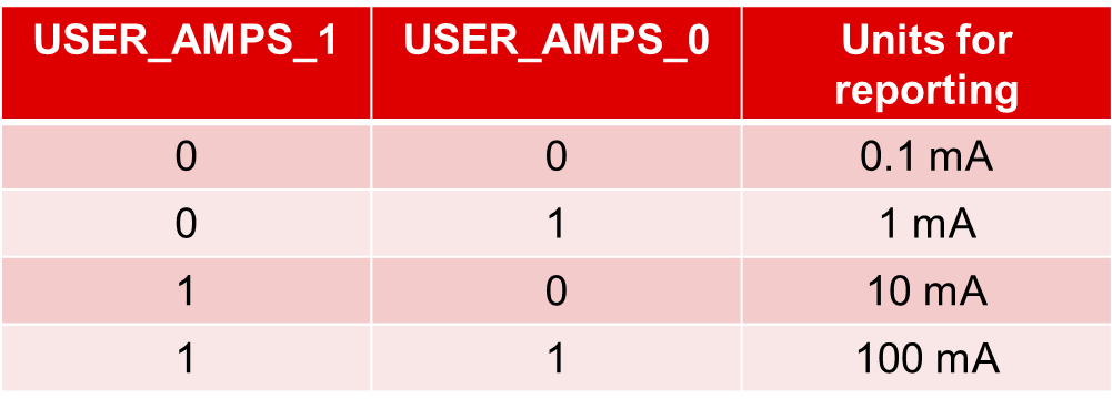
The BQ76942 and BQ76952 provide selectable units for current measurements in order to accommodate different ranges of current levels. For example, when using units of 1 mA, the CC1 Current() reported in 16-bit format can represent currents between -32.768 A and +32.767 A. If higher currents are expected, the units can be changed to 10 mA, which then allows representation of currents ranging from -327.68 A to +327.67 A.
As shown in Table 1, the Settings:Configuration:DA Configuration:[USER_AMPS_1:0] configuration settings set the units. These units apply to the CC2 Current(), CC1 Current() and CC3 Current() values.
|
The BQ76942 and BQ76952 require a current gain value (Calibration:Current:CC Gain and Calibration:Current:Capacity Gain) to convert the voltage measured across the sense resistor into a current value. You can set these gain values based on the nominal value of the sense resistor used in the system, or calibrate them for each printed circuit board (PCB) for storage in device memory. The devices also include a setting for board-level offset current, which can be determined for each PCB and stored in memory. It is possible to capture a number of measurements on the manufacturing line (with the number of samples set in Calibration:Current Offset:Coulomb Counter Offset Samples), with the sum of the measurements stored in Calibration:Current Offset:Board Offset. The device will subtract a value of Board Offset/Coulomb Counter Offset Samples from each reading before scaling by CC Gain when reporting current.
Synchronized voltage and current measurements
The BQ76942 and BQ76952 support synchronized measurements using two delta-sigma ADCs to measure current and each cell voltage simultaneously. The 24-bit raw ADC readings for each cell voltage and the synchronized current are stored in the device and can be read out as a synchronized pair. You can use this data to analyze cell impedances or interconnect resistances.
Accumulated charge measurement
The BQ76942 and BQ76952 continuously integrate the Coulomb counter current data to generate the accumulated charge value; the host can reset this integrator on demand using subcommand 0x0082 RESET_PASSQ(). The devices also include a timer in units of seconds, which resets at the same time as the Coulomb count integration. Dividing the accumulated charge value by the timer will calculate the average current over the time interval since the timer started.
The accumulated charge is provided as two 32-bit values. The first 32-bit (signed) data reports the charge in units of userAh, while the second 32-bit (unsigned) data reports the fractional charge in units of userAh/232. The 64-bit accumulated charge data and timer value are all reported by the 0x0076 DASTATUS6() subcommand.
The BQ76942 and BQ76952 battery monitors and protectors implement a high-performance measurement subsystem that includes a precision Coulomb counter. The current measurement subsystem in these devices is highly configurable, enabling you to make a trade-off between speed and resolution. Multiple current readings are available, each optimized for gauging, post-processing and current-based battery-pack protection.
Additional resources
- Read the related technical articles on voltage measurement and temperature measurement.
- Read the application report, “Easy Configuration of BQ76942/52 Battery Monitors.”
- Watch the training video, “What is the secret sauce behind Impedance Track?”
IMPORTANT NOTICE AND DISCLAIMER
TI PROVIDES TECHNICAL AND RELIABILITY DATA (INCLUDING DATASHEETS), DESIGN RESOURCES (INCLUDING REFERENCE DESIGNS), APPLICATION OR OTHER DESIGN ADVICE, WEB TOOLS, SAFETY INFORMATION, AND OTHER RESOURCES “AS IS” AND WITH ALL FAULTS, AND DISCLAIMS ALL WARRANTIES, EXPRESS AND IMPLIED, INCLUDING WITHOUT LIMITATION ANY IMPLIED WARRANTIES OF MERCHANTABILITY, FITNESS FOR A PARTICULAR PURPOSE OR NON-INFRINGEMENT OF THIRD PARTY INTELLECTUAL PROPERTY RIGHTS.
These resources are intended for skilled developers designing with TI products. You are solely responsible for (1) selecting the appropriate TI products for your application, (2) designing, validating and testing your application, and (3) ensuring your application meets applicable standards, and any other safety, security, or other requirements. These resources are subject to change without notice. TI grants you permission to use these resources only for development of an application that uses the TI products described in the resource. Other reproduction and display of these resources is prohibited. No license is granted to any other TI intellectual property right or to any third party intellectual property right. TI disclaims responsibility for, and you will fully indemnify TI and its representatives against, any claims, damages, costs, losses, and liabilities arising out of your use of these resources.
TI’s products are provided subject to TI’s Terms of Sale (www.ti.com/legal/termsofsale.html) or other applicable terms available either on ti.com or provided in conjunction with such TI products. TI’s provision of these resources does not expand or otherwise alter TI’s applicable warranties or warranty disclaimers for TI products.
Mailing Address: Texas Instruments, Post Office Box 655303, Dallas, Texas 75265
Copyright © 2023, Texas Instruments Incorporated