SSZT342 february 2020 UCC12050
While you may already have a good idea of what isolation is, perhaps you have questions about the various types. In this technical article, I’ll define the four major types of isolation and explain how engineers can benefit from TI’s new fully integrated transformer technology, which delivers several advantages compared to other reinforced isolation solutions.
Simply put, isolation blocks unwanted DC and AC currents between separate parts of a system while transferring desired signals and/or power. Designers will apply isolation in many applications to power high-side gate drivers in power or motor-drive circuits, protect low-voltage circuits in high-voltage systems (such as processors in electrical automotive systems), separate communication between systems with different voltage potentials, or prevent electrical shock to end users of high-voltage equipment. Many different levels of isolation exist, including functional, basic, double and reinforced isolation.
Functional isolation, as the name suggests, merely provides a function. It passes a signal or power from a system at one voltage potential to another system and a different voltage. It does not protect against electrical shock.
Basic isolation is the next step up. It is functional isolation, but adds electrical shock protection. Class I devices use functional isolation along with an earth ground connection to protect users. Figure 1 shows a typical Class I device.
 Figure 1 Typical Class I device
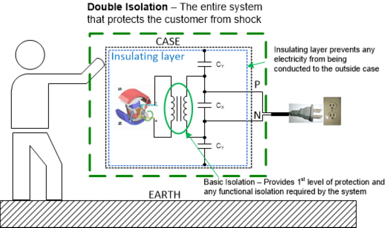
Double isolation takes a system with basic isolation (the basic level of protection against electrical shock) and adds a supplementary insulation layer between the electrical parts and the end user to reduce the likelihood of electrical shock in the event that basic isolation fails. Class II products require double isolation. These products are manufactured with AC plugs that do not have the earth ground prong on them, which improves the safety of the product because it does not depend on external wiring for user safety. Examples of end equipment with double isolation include grid asset monitoring systems, portable medical devices like IV pumps, and electrical devices like blenders or charging supplies for cellphones.
A second layer physically insulates internal metal parts (that could become live) from external casing, or uses a nonconductive external casing like plastic. Class II devices do afford some amount of safety vs. Class I devices because they do not depend on external wiring to provide redundant protection. Figure 2 illustrates a typical Class II device.
 Figure 2 Typical Class II device
Reinforced isolation achieves the same result as double isolation using a single layer. A device with reinforced isolation provides basic isolation; plus, it is designed to ensure physical separation between printed circuit board traces, cores, windings, pins, etc., while meeting safety creepage and clearance distances (which refer to a physical distance between two voltage systems). A reinforced device is designed with double isolation, but can only be tested as a single piece.
Safety standards define values that must achieved for certification. For example, International Electrotechnical Commission (IEC) 60950-1 requires a creepage/clearance distance for basic isolation of 3.2 mm and a creepage/clearance distance for reinforced and double isolation of 6.4 mm. The voltage rating requirements for basic insulation are 2,500 VRMS for 1 minute and 3,000 VRMS for 1 second; for reinforced and double isolation, they are 5,000 VRMS for 1 minute and 6,000 VRMS for 1 second. You can see that reinforced/double isolation is exactly that – double the basic isolation. Double isolation devices are indicated on the label with a double-box insignia, as shown in Figure 3.
 Figure 3 Double isolation insignia
Once you’ve decided to build a Class II device, you’ll need double or reinforced isolation. Why choose one type over another? The answer lies in the size and cost of your solution. As you could imagine, a single device that does the job of two lends itself to a physically smaller solution. You’ll achieve cost savings not only through integration into a single device, but in the reduction of engineering required to meet the isolation safety standard.
Fully integrated, reinforced isolation solutions are available in small packages, and they’re easy to implement. Such devices have several benefits compared to other solutions. For example, the Texas Instruments UCC12050 integrates all of the control, drivers, field-effect transistors and magnetics into a single package. You need only to place the device on the board with some bypass capacitors and follow the directions for proper board layout to design a reinforced isolated solution to bias supply applications in a super-small footprint. All of the engineering work has been done: no magnetics design, no supply controller selection.
Standards like Verband der Elektrotechnik (VDE) 0884-10 and International Electrotechnical Commission (IEC) 60747-17 provide the minimum requirements for reinforced isolation device certification. The UCC12050 fulfills all of the requirements for reinforced isolation, with minimum protections of 7 kVPK (for 1 second, production tested) and 5 kVRMS (for 1 minute) of isolation.
In summary, functional and basic isolation electrically isolate one voltage rail from another, while double and reinforced isolation offer interchangeable solutions to the same design goal – removing the earth ground pin from the plug.
Reinforced isolation provides a benefit over double isolation by reducing two insulating devices to one. It is a good choice in your system to save time, effort, space and possibly cost over other isolated bias supply solutions.
Additional resources:
- Read the white paper, “Power Through the Isolation Barrier: The Landscape of Isolated DC/DC Bias Power Supplies.”
- Download the UCC12050 data sheet.
- See the application note, “A Reinforced-isolated Analog Input Chain for Space-Constrained Applications.”