SSZT409 september 2019 UCC20225-Q1
Starter-generator systems are at the heart of 48-V mild hybrid (MHEV) vehicle architectures, and therefore are at the heart of the second automotive revolution. The high-energy recuperation potential of these new systems, coupled with advances in 48-V lithium-ion battery technology, reduces carbon dioxide emissions from combustion engines. Adoption of 48-V systems also increases the power-supply capacity of the vehicle and enables new vehicle features that are compact, lighter and lower cost.
Starter-generator systems:
- Provide high starting torque in combustion engines.
- Regenerate energy during cruising and braking of the vehicle (generator mode).
- Provide torque assistance to the internal combustion engine or act as the prime mover for the vehicle at low speeds (motor mode).
The first generation of starter-generator systems focused on scaling up existing 12V alternator systems. The most common of these is the P0 configuration, which involves a belt-driven starter-generator system capable of peak power levels <15 kW and peak starting torques in the range of 150 Nm at the motor. Besides scaling up the voltage and power levels of existing 12-V systems, the transfer of power occurs through a belt connection versus a pinon-gear-based system. The choice of motors for P0 systems was also influenced by decades of experience and proven field reliability of synchronous claw-pole motors and asynchronous induction motors from 12-V architectures.
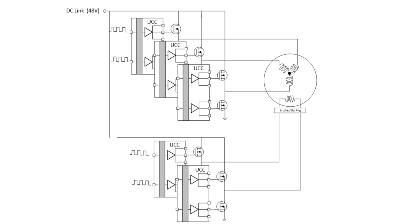
A claw-pole motor is essentially a three-phase brushed motor: the stator comprises windings that are electrically excited with three-phase AC current and the rotor is excited with DC current to create its magnetizing poles. Slip rings or brushes transfer power to the rotor. The electronics for these systems involve a three-phase half-bridge inverter for creating the AC current for the stator windings and a standard full H-bridge for driving the DC excitation for the rotor winding. A dual output driver like TI’s UCC20225-Q1 gate driver is an excellent fit for these topologies, with their robust high voltage and drive capability. Five UCC20225-Q1 gate drivers efficiently drive the three stator coils and two rotor excitation coils in this kind of system (see Figure 1).
 Figure 1 Five-phase claw-pole motor
driven with five UCC20225-Q1 gate drivers in a half-bridge configuration
Figure 1 Five-phase claw-pole motor
driven with five UCC20225-Q1 gate drivers in a half-bridge configurationWhile P0 systems offer the best cost and ease of integration into existing drivetrains, the carbon dioxide reduction is limited to <10% due to limitations on power transfer across the belt and losses due to drivetrain friction. The next level involves integrated starter generators or P2/P3/P4 architectures, which involve tighter mechanical integration into the drivetrain and elimination of the belt. These efforts push the limits of carbon dioxide reduction to about 15% by increasing power levels to the 20-KW range.
Mechanical integration into the drivetrain changes the demands on the motor. The motor now has to be flatter for crankshaft integration between the engine and the transmission. The motors must also have higher power density and torque as well as the ability to operate under dynamic load, temperature and environmental conditions when mounted inside or close to the transmission. Claw-pole and AC induction motors do not lend themselves well to these configurations, and the industry is fast moving toward brushless permanent magnet (PMSM) motors. PMSM motors offer high power densities and tighter packaging. The elimination of brushes also enables them to be cooled by transmission oil when integrated in the transmission.
The electronics for brushless PMSM motors are similar to the stator electronics for a claw-pole or AC induction motor. The use of permanent magnets eliminates the need for DC excitation drivers and the system can operate with a three-phase inverter, as shown in Figure 2.
 Figure 2 Three-phase PMSM motor driven
with three UCC20225-Q1 gate drivers in a half-bridge configuration
Figure 2 Three-phase PMSM motor driven
with three UCC20225-Q1 gate drivers in a half-bridge configurationThe adoption of PMSM motors creates a unique challenge to designers of these systems, however. When in generator mode, all motors (DC-excited or PM) are capable of creating high voltages in the inverter bridge. While this is the intended functionality in generator mode, it is an undesirable effect during system failure. Since the generator will continue to rotate at high rpms in spite of this failure, the voltage can rise to extremely high levels. Lithium-ion batteries have the safety goal of preventing battery operation outside voltage and temperature safety limits. The system is expected to meet the ISO26262-2:20118 standard, Automotive Safety Integrity Level-D capability for this goal.
For DC-excited motors, one solution is to de-energize and demagnetize the rotor by cutting power to the excitation full bridge. In some cases this may be sufficient, if the demagnetization is fast enough and the energy can be suppressed. In PMSM motors, however, demagnetization is not an option. The industry is actively exploring alternate methodologies to suppress this effect.
As electric vehicle/hybrid electric vehicle innovation continues, safety goals for 48-V motor-generator systems will continue to evolve around three core themes:
- The prevention of overvoltage of the DC link (48-V).
- Unintended motor assistance of the drivetrain.
- Loss of motor assistance to the drivetrain.
Additional resources
- Review TI motor drivers that meet industry-standard functional safety requirements.
- Read the white paper, “Analog components advance functional safety development for automotive applications.”
- Check out our Automotive 48-V 1-kW Motor Drive Reference Design.