SSZT421 august 2019
Because elevators transport millions of people every day, operational safety is of prime importance. Have you ever thought about what happens when the mains supply to the elevator shuts down? Will the elevator drop down the hoist way, or get stuck somewhere between landing doors? To prevent the first consequence, fail-safe braking mechanisms ensure that the elevator car comes to a stop as soon as the mains power goes off. After stopping, to keep those inside the elevator from being stuck inside until the power comes back on, an automatic rescue device (ARD), also called the elevator emergency power supply, comes into play.
The ARD is a backup power unit that continuously monitors the elevator mains supply. An unexpected shutdown may occur because of a power-grid fault or if faulty wiring breaks the input phase to the elevator drive. The ARD detects such fault conditions, immediately begins powering the elevator drive and sends a fault signal to the elevator controller. The controller then releases the motor drive brake and slowly brings the car to the closest landing door. The direction of the car is based on what will take the least amount of power to bring it to the landing door. Once at the closest floor, the elevator door opens and an audio/visual indicator indicates that it’s safe to exit. After a pre-defined time, the elevator door closes again and the supply to the elevator drive shuts down.
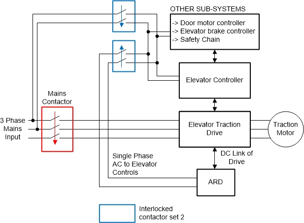
Figure 1 illustrates the connection from a conventional ARD into the elevator system. A three-phase mains supply connects to the traction drive through a mains contactor. The mains contactor is interlocked with the ARD contactor, which connects the output of ARD to the traction drive. Interlocking ensures that both contactors do not turn on simultaneously, avoiding any shorting of mains with the ARD output. A single-phase output tapped from the mains supplies the rest of the elevator system components through the contactor, like the controller, door motor control, brakes and safety chain.” The contactor is also interlocked with the ARD’s single-phase output contactor. During normal operation, the ARD charges the backup battery; its inverter output is disconnected from the elevator system. A power shutdown switches on the interlocked contactors and the ARD powers the elevator system.
 Figure 1 Conventional ARD system
connection in an elevator
Figure 1 Conventional ARD system
connection in an elevatorThe ARD system shown in Figure 2 has an AC/DC charger power stage to charge the battery. A DC/DC converter boosts the battery voltage to a high voltage and a DC/AC inverter generates an AC output to power the elevator traction drive and elevator controls. A circuit continuously monitors the AC mains input for blackout and single-phase conditions and enables or disables the required power stages inside the ARD.
 Figure 2 Conventional ARD
system
Figure 2 Conventional ARD
systemAnother approach is to use a bidirectional DC/DC converter like the 2kW, 48V to 400V, >93% Efficiency, Isolated Bidirectional DC-DC Converter Reference Design for UPS to implement an ARD, as shown in Figure 3 and Figure 4. Such a converter can transfer energy from both directions. In an ARD, the converter connects directly to the DC link of the elevator traction drive. During normal operation, the converter works like a battery charger, charging the battery from the DC link. When there is no mains power, the converter works like a boost converter powering the DC link from the battery. Another inverter stage inside the ARD generates a single-phase AC voltage for the controls.
 Figure 3 An ARD system with a
bidirectional DC/DC converter connected into an elevator system
 Figure 4 An ARD with a bidirectional
DC/DC
Figure 4 An ARD with a bidirectional
DC/DCComparing the two approaches, Table 1 shows how the bidirectional DC/DC converter approach offers more benefits.
| Parameter | Conventional ARD system using an uninterruptible power supply (UPS) | ARD system with a bidirectional DC/DC converter |
|---|---|---|
| No. of converter stages |
Three:
|
Two:
|
| Efficiency |
Lower efficiency:
|
High efficiency:
|
| Cost |
High:
|
Low:
|
Typical battery voltages for an elevator ARD are 24 V, 36 V, 48 V and 60 V. The nominal DC link voltage for a three phase 400-VAC-powered elevator traction drive is ~600 V. The isolated bidirectional DC/DC converter reference design is a 2-kW, 48-V to 400-V, digitally controlled bidirectional power stage operating as a half-bridge battery charger and current-fed full-bridge boost converter in the opposite direction. The design is scalable to different power levels and input battery voltages by simply redesigning the transformer and selecting appropriately rated metal-oxide semiconductor field-effect transistors.
Additional resources
- Learn more about the reference design discussed in this article by watching the video, “2-kW isolated bidirectional DC/DC converter reference design for UPS.”
- Explore TI’s elevators and escalators portfolio.