-
Achieving Accuracy in Bin Picking with TI DLP® Technology-powered Structured Light Systems
Achieving Accuracy in Bin Picking with TI DLP® Technology-powered Structured Light Systems
Franz Schellhase
In an industrial environment, parts of different shapes, size, material, and optical properties (reflectance, absorption, etc.) need to be handled every day. These parts have to be picked and placed in a specific orientation for processing, and the automation of these pick and place activities from an environment (containers or other) where the parts are randomly held is generally referred to as bin picking. This task poses the challenge for a robot end effectors (devices that are attached to the end of a robotic arm) to know the exact 3D location, dimensions and orientation of the objects it wants to grip. In order to navigate around the walls of the box and other objects inside the box, the robot’s machine vision system needs to acquire depth information in addition to the 2D camera information.
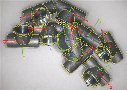
The challenge of the 3D-image capture of objects for bin-picking can be addressed by a structured light technique. The structured light technology-based 3D scanner/camera works by projecting a series of patterns onto the object being scanned and captures the pattern distortion with a camera or sensor. A triangulation algorithm then calculates the data and outputs a 3D-point cloud. Image processing software like Halcon by MVTech calculates the objects position and the robot arm’s optimal approach path (Figure 1).
 Figure 1 Example of matching pipe
couplings with their respective 3D model using Halcon (Source: Halcon by
MVTech)
Figure 1 Example of matching pipe
couplings with their respective 3D model using Halcon (Source: Halcon by
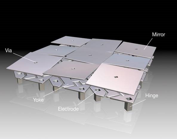
MVTech)DLP technology provides a high speed pattern projection capability through a micro-mirrors matrix assembled on top of a semiconductor chip know as a digital micro-mirror device (DMD) as depicted in Figure 2. Each pixel on the DMD represents one pixel in the projected image, allowing pixel accurate image projection. The micro-mirrors can be transitioned at ~ 3us to reflect the light incident on the object through a projection lens or onto a light dump. The former achieves a bright pixel on the projected scene, while the later create a dark pixel. DLP technology also offers unique advantage with its ability to project patterns over a wide wavelength range (420 nm – 2500 nm) using various light sources like lamps, LEDs and lasers.
DLP technology- powered structured light for bin picking offers several advantages:
- Robust against environmental lighting. Lighting conditions in factories like low light exposure and high contrast between differently lit areas causing underexposure of sensors or flickering light posing interference to machine vision systems can be a challenge in applications that need machine vision like bin picking. DLP technology-powered structured light has inherent active lighting, which makes it robust against those conditions.
- No moving parts. Structured light systems capture the whole scene at once, avoiding the need to either sweep a light beam over objects or move objects through a beam (like in scanning solutions). A structured light system protects doesn’t use moving parts in a macroscopic scale making it immune to wear and tear through mechanical deterioration.
- Real-time 3D image acquisition. The micromirrors in DLP chips are controlled at high speeds offering custom pattern projection at up to 32 kHz. In addition to this, the DLP controllers provide trigger output and inputs for use in synchronizing cameras and other devices with the projected pattern sequence. These features help with enabling real-time 3D image acquisition allowing simultaneous scanning and picking.
- High contrast and resolution of projected patterns. Because each micromirror either reflects light onto the target or onto an absorption surface, high contrast ratios are achieved enabling accurate point detection that is independent of the object’s surface properties. Complemented by the availability of high-resolution DLP chips with up to 2560 x 1600 mirrors, objects down to the micron level can be detected.
- Adaptable to object parameters. Programmable patterns and various point-coding schemes like phase shifting or gray coding make structured light system more adaptable to object parameters than systems using diffractive optical elements.
- Accelerated development time. While robots offer high repeatability, bin picking requires accuracy in an unstructured environment, where picking objects keep shifting positions and orientations each time one of them is removed from the storage bin. Working successfully with this challenge requires a reliable process flow, from machine vision to computing software to the robot’s dexterity and gripper. Making everything work in conjunction can be a challenge that consumes a lot of development time.
 Figure 2 DLP chips contain millions of
micromirrors that are individually controlled at high speeds and deliberately
reflect light to create projected patterns
Figure 2 DLP chips contain millions of
micromirrors that are individually controlled at high speeds and deliberately
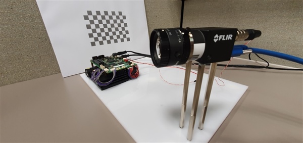
reflect light to create projected patternsTI’s evaluation modules for DLP technology enable fast implantation of structured light into the machine vision workflow. To demonstrate this capability, Factory Automation and Control systems engineers mounted a DLP LightCrafter 4500 evaluation board at a set distance and angle to a monochromatic camera. The DLP evaluation board is triggered by the camera through a trigger cable connecting the two to each other; see Figure 3.
 Figure 3 Structured light setup
including the DLP Products LightCrafter 4500 (left), a Point Grey
forward-looking infrared Flea3 camera (right) and calibration (back)
Figure 3 Structured light setup
including the DLP Products LightCrafter 4500 (left), a Point Grey
forward-looking infrared Flea3 camera (right) and calibration (back)Both the board and camera are connected to a PC via USB, and the whole setup is directed at a calibration board. Software from the Accurate Point Cloud Generation for 3D Machine Vision Applications Using DLP® Technology reference design is then used to calibrate the camera and projector for parameters like focal length, focal point, lens distortion, translation and rotation of the camera relative to the calibration board. The reference design user guide walks through the process step by step.
Recalibration is only necessary if the camera is moved relative to the DLP products board.
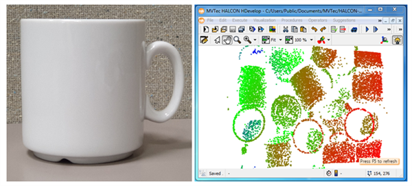
After the setup is complete, it’s possible to create point clouds of real-world targets. Those clouds are output by the software in an arbitrary file format, which is then read and displayed by some brief code developed in Halcon’s HDevelop platform. Figure 4 shows a point cloud with color coding for depth information taken of a box filled with coffee mugs.
 Figure 4 Captured mug (left) and
acquired point cloud acquired with DLP powered structured light of several mugs
in a box displayed in Halcon HDevelop (right)
Figure 4 Captured mug (left) and
acquired point cloud acquired with DLP powered structured light of several mugs
in a box displayed in Halcon HDevelop (right)Halcon’s surface matching can determine the mug’s 3D pose by comparing the point cloud with a 3D CAD model of a mug. Doing this the robot arm now “sees” the object and the optimal approach path of the robot arm can be calculated allowing it to pick objects from boxes avoiding obstacles in an unstructured and changing environment.
Additional resources
- Learn more about “Highly Scalable TI DLP Technology for 3D Machine Vision.”
- Read the white paper, “High-accuracy 3D scanning using Texas Instruments DLP technology for structured light.”
- Learn more about TI DLP technology.
IMPORTANT NOTICE AND DISCLAIMER
TI PROVIDES TECHNICAL AND RELIABILITY DATA (INCLUDING DATASHEETS), DESIGN RESOURCES (INCLUDING REFERENCE DESIGNS), APPLICATION OR OTHER DESIGN ADVICE, WEB TOOLS, SAFETY INFORMATION, AND OTHER RESOURCES “AS IS” AND WITH ALL FAULTS, AND DISCLAIMS ALL WARRANTIES, EXPRESS AND IMPLIED, INCLUDING WITHOUT LIMITATION ANY IMPLIED WARRANTIES OF MERCHANTABILITY, FITNESS FOR A PARTICULAR PURPOSE OR NON-INFRINGEMENT OF THIRD PARTY INTELLECTUAL PROPERTY RIGHTS.
These resources are intended for skilled developers designing with TI products. You are solely responsible for (1) selecting the appropriate TI products for your application, (2) designing, validating and testing your application, and (3) ensuring your application meets applicable standards, and any other safety, security, or other requirements. These resources are subject to change without notice. TI grants you permission to use these resources only for development of an application that uses the TI products described in the resource. Other reproduction and display of these resources is prohibited. No license is granted to any other TI intellectual property right or to any third party intellectual property right. TI disclaims responsibility for, and you will fully indemnify TI and its representatives against, any claims, damages, costs, losses, and liabilities arising out of your use of these resources.
TI’s products are provided subject to TI’s Terms of Sale (www.ti.com/legal/termsofsale.html) or other applicable terms available either on ti.com or provided in conjunction with such TI products. TI’s provision of these resources does not expand or otherwise alter TI’s applicable warranties or warranty disclaimers for TI products.
Mailing Address: Texas Instruments, Post Office Box 655303, Dallas, Texas 75265
Copyright © 2023, Texas Instruments Incorporated