SSZT437 July 2019 AWR2243 , TDA2SX
Radio Detection And Ranging (RADAR) systems have been used in many applications for several decades, including everything from weather prediction to law enforcement, with automotive showing up around the turn of the 21st century. This article examines a typical automotive use case and corresponding trends.
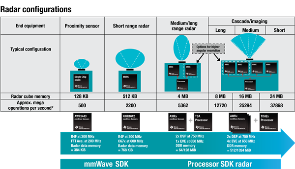
There are millions of 24 GHz-based radar systems on the road today and more coming based on the next generation, 76-81 GHz systems (e.g. TI’s RFCMOS AWRx product line). From a high-level view, radar system configurations are divided into the end equipment categories shown in Figure 1 and are further segmented by the effective range (distance) they address, which translates into ~1 meter to 400 meters for Proximity to Long Range systems respectively.
 Figure 1 CMOS*-Based Radar
Configuration Overview
Figure 1 CMOS*-Based Radar
Configuration Overview(*Complementary Metal Oxide Semiconductor)
As the effective range and required accuracy increases, the need for additional processing is generally required as indicated via the appearance of a processor, along with additional radar (MMIC) devices, in the above CMOS-based Radar Configuration Overview (Figure 1). The associated memory with the additional processor also significantly increases the system’s memory performance further elevating capabilities.
A typical system is a forward-facing, medium-to-long range radar system used to provide detection and ranging in the forward path of a moving vehicle. This Adaptive Cruise Control system automatically adjusts the speed of the vehicle based on spacing between the car with the system and the vehicle(s) in front of it. The accuracy of this type of system is critical to the safe operation of a vehicle under its control. Using multiple MMICs and a processor can significantly increase the angular resolution and range. The processor performs calculations on streaming data from multiple MMICs which increases angular and range resolution along with overall detection distance as well.
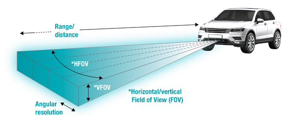
A system using multiple MMIC devices and a processor to provide further downstream calculations constitutes a Cascade / Imaging Radar (CIR) system. These programmable systems can provide the functionality of multiple types of radar systems (e.g. short, medium & long range) via software algorithms running on the processor, configurations of the associated MMICs, and the antenna design. In addition to this flexibility, these CIR systems greatly increase operational safety using beam-forming techniques to extend the range and resolutions in a long-range scenario as well as MIMO (Multiple-Input & Multiple-Output) techniques to refine the degree of angular resolution as the region of interest becomes closer in range (see Figure 2). These techniques enhance system efficacy by increasing the detection distance, range resolution and angular resolution/accuracy relative to the objects in front of the vehicle.
 Figure 2 Automotive Perception
Terminology
Figure 2 Automotive Perception
TerminologyFigure 3 shows the various steps to facilitate object detection from the raw data being sent by the MMICs. In the case of a 4-chip CIR system like TI’s recently released ‘Cascade / Imaging Radar Capture & Fusion Platform using Jacinto™ ADAS Processor’, there is a significant amount of processing required for each data stream produced by the MMIC (TI mmWave AWR2243 sensors) devices. A single SoC from TI’s automotive ADAS processors product line can easily meet these processing requirements. One ‘TDA2SXBTQABCQ1’ can efficiently provide all of this processing with margin by utilizing its heterogeneous architecture containing several types of CPUs: 4x SIMD (EVE), 2x DSP (C66), and 6x Arm® Cortex® (2x A15, 4x M4) cores.
 Figure 3 Radar Data Processing
Flow
Figure 3 Radar Data Processing
FlowFigure 3 also shows how the radar processing flow is mapped across these cores. The color coding in the numbered circles corresponds to the core(s) performing each of the specific operations (blue = C66, green = EVE). The Arm cores execute general application management and overall control code for the system. Figure 4 below shows a different, higher-level view of how the processing is partitioned on the TDA2SX device being used in TI’s 4-chip CIR reference design.
 Figure 4 Radar Data Processing Flow
Partition
Figure 4 Radar Data Processing Flow
PartitionProcessing requirements increase as the complexity and capability of the radar systems increase. Figure 5 shows how the typical radar cube memory increases along with the required operations (millions). This complexity and processing will increase over time and drive the need for more processing capabilities as the below trends continue in the automotive space. Together, TI’s radar MMICs (AWRx) and ADAS processors (TDAx) can address these needs with unique architectures, technologies and software development kits (SDKs). Selecting, developing and productizing a system utilizing scalable product families, such as TI’s TDA ADAS processing family, help to address these ongoing trends in a manner that reduces overall development time and increases system efficiency.
 Figure 5 Radar Configuration with
Memory and Processing Trends
Figure 5 Radar Configuration with
Memory and Processing TrendsThe possible integration of short, medium, and long-range systems into a single CIR system can reduce the overall number of systems in the vehicle along with the associated power consumption, supporting power supply design and costs. Performance gains via the processor can also potentially reduce cost/need of companion systems, e.g. minimizing camera resolution/frame rate requirements and ultrasonic sensor(s) reduction/removal.
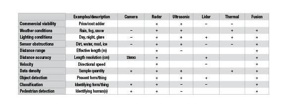
In addition to the radar-specific trend, there is an overall trend of using multiple sensors on vehicles to enhance functional safety through the fusion of different modalities; helping offset the many environmental variations these systems must handle appropriately (Figure 6). The below table provides insight into which sensors best address the various conditions relevant to typical vehicle perception. No single sensor addresses all of these requirements, justifying the fusion of various sensor data to promote greater perception accuracy.
 Figure 6 Sensor Pros (+) and Cons (-)
Table
Figure 6 Sensor Pros (+) and Cons (-)
TableThe trends referenced above will require the need for increased processing speed/efficiency and readily addressed by TI’s TDAx ADAS processors product line.
Additional Resources:
- Make your imaging radar design a reality by downloading our reference designs using Jacinto processors and TI mmWave sensors.
- Learn more about Jacinto™ ADAS automotive processors.
- Read about tips for designing a robust computer vision system for self-driving cars in this technical article.
- Download our white papers to learn more about ADAS technology: