-
Do All Rails Need Low Iq?
Do All Rails Need Low Iq?
Chris Glaser

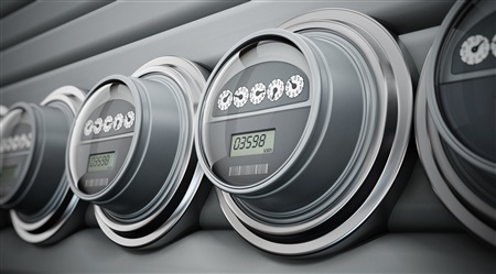
A smart meter
All designers of ultra-low power systems are concerned about battery life. How much time will elapse before the battery in a fitness tracker will need recharging? Or, for primary cell systems, how long will it be before a technician must service the smart meter and change the battery? Clearly, the design goal is maximum battery runtime. For a fitness tracker, a week of runtime may be good, but a smart meter operates for 20 years or more. What do you need to consider in each of the various subsystems to achieve this runtime?
In many systems, one or two voltage rails are always enabled. These power the system microcontroller (MCU), a critical sensor or maybe a communication bus. These always-on rails need to have very high efficiency to extend the battery runtime. A good subsystem design reduces the current drawn by each of the always-on subsystems to a minimum – many times this is less than 10 µA, or even 1 µA, total. An ultra-low power supply is required to reap the benefits of these subsystem optimizations. In rails with very low current consumption, this translates to a power supply with ultra-low quiescent current (IQ), such as the 60 nA IQ TPS62840.
You might be tempted to think that it’s most important to minimize the current consumption of each of the power supplies while they are running. Reducing the IQ increases efficiency and thus extends the battery runtime by consuming less battery power. But is the efficiency increase always significant? For systems that operate at relatively higher load currents, such as displays and some sensors, the answer is clearly no; the output power is much greater than the IQ power. For example, if the display in a fitness tracker draws 12 V at 5 mA (60mW total), the 100µA IQ drawn from the 3.6V battery (0.36 mW total) is insignificant.
More important for these types of subsystems is the power consumption when disabled. An ultra-low power system turns off power-hungry subsystems most of the time in order to conserve the battery. Thus, the shutdown current becomes critical to the system’s battery life. This leakage current, as it is frequently called, may be so high that you will have to add a load switch to disconnect the subsystem from its power source to further reduce its shutdown current. The TPS62748, high efficiency buck converter, provides both a load switch and 360 nA ultra-low IQ for such systems.
When a load switch is not used, you must consider both the leakage current into the device itself and its load if there is a path to the load through the device. This is frequently the case with a boost converter, so specific circuitry is sometimes added to break this path, such as the isolation switch in the TPS61046, boost converter. In other cases, this path is specifically optimized to allow bypass operation – powering the load with less than 50 nA of shutdown current consumption in the disabled device.
It’s important to pick the right type of device – ultra-low IQ or ultra-low shutdown current – for your specific subsystem. These nuances are prevalent in every ultra-low power system, from a wearable to a smart meter to a medical device, so consider the requirements of your application wisely before choosing the optimal solution.
Additional Resources:
- Read more about "Low Iq: What it is, what it isn’t, and how to use it."
- Learn the tricks of using WEBENCH® to design near 100% duty-cycle for ultra-low power applications.
- Consider this TI Design for smart meters.
- Explore the nuances in ultra-low power designs for wearable products.