-
Imaging Radar: One Sensor to Rule Them All
Imaging Radar: One Sensor to Rule Them All
Amit Benjamin
There is still some confusion in the industry about the different roles that three major sensor types – camera, radar and LIDAR – have in a vehicle, and how each can solve the sensing needs of advanced driver assistance systems (ADAS) and autonomous driving.
Recently, I had an interesting discussion with one of my friends, who knows I work with TI millimeter-wave (mmWave) sensors for radar in ADAS systems and autonomous vehicles (AVs).
My friend doesn’t skip an opportunity to tease me any time he reads about how an autonomous vehicle performed in different driving situations, like obstacle detection. Here’s how one conversation went:
Matt: “If that car had LIDAR, it would have easily identified the object in the middle of the lane.”
Me: “As always, I disagree.”
Matt: “What?! Why would you disagree? There was a camera sensor and a radar sensor in that vehicle, and still the ADAS system totally missed the vehicle in the middle of the lane.”
Me: “When you read about these recent events, you’ll notice that the cameras are often exposed to glare or other elements that cause the camera to miss an object in the road. Cameras are sensitive to high-contrast light and poor visibility conditions, such as rain, fog and snow. In this case, the radar sensor probably did identify the target.”
Matt: “Still, we keep running into different situations that these ADAS and AV systems seem to find very challenging. What is missing?”
Me: “It seems the ADAS’ decision-making system relied on the camera as the primary sensor to decide if the target was really there, or whether it was a false alarm.”
Matt: “So the car’s radar and camera can’t be trusted. So you are left with LIDAR as the only reliable sensor. Isn’t that right?”
Me: “Not quite. LIDAR is not as sensitive to visibility conditions as the camera is, but it is sensitive to weather conditions like fog, rain and snow. In addition, LIDAR is still considered to be very expensive, which probably limits its usage initially to higher-end level 4 and 5 autonomous vehicles.”
Matt: “So we are doomed! There is no single sensor that can make autonomous vehicles truly reliable. We will always need all three, which means very expensive autonomous vehicles.”
Me: “You are partly right. Level 4 and 5 autonomous vehicles will probably need all the three sensors – camera, LIDAR and radar – to provide high reliability and a fully autonomous driving experience.
However, for more economic vehicles requiring partial autonomy at levels 2 and 3, where high-volume mass production has already started, imaging radar using TI mmWave sensors delivers the high performance and cost-effectiveness that can enable broad adoption of ADAS functionality.”
So What Is Imaging Radar?
As I explained to Matt, imaging radar is a subset of radar that got its name due to the clear images that its high angular resolution is capable of providing.
Imaging radar is enabled by a sensor configuration in which multiple low-power TI mmWave sensors are cascaded together and operate synchronously as one unit, with many receive and transmit channels to significantly enhance the angular resolution as well as the radar range performance. mmWave sensors, when cascaded together, can reach an extended range of up to 400 m using integrated phase shifters to create beamforming. Figure 1 shows the cascaded mmWave sensors with their antennas on an evaluation module.
 Figure 1 An Imaging Radar Evaluation Module with Four Cascaded TI mmWave Sensors
mmWave Technology for Imaging Radar
The main reason why the typical radar sensor hadn’t been considered the primary sensor in vehicles until recently is its limited angular resolution performance.
Angular resolution is the ability to distinguish between objects within the same range and the same relative velocity.
A common use case that highlights the imaging radar sensor’s advantage is being able to identify static objects in high resolution. The typical mmWave sensor has a high velocity and range resolution, which enables it to easily identify and differentiate between moving objects, but it is quite limited when it comes to static objects.
For example, in order for a sensor to “see” a stopped vehicle in the middle of the lane and distinguish it from light poles or a fence, the sensor requires a certain angle resolution in both the elevation and azimuth. .
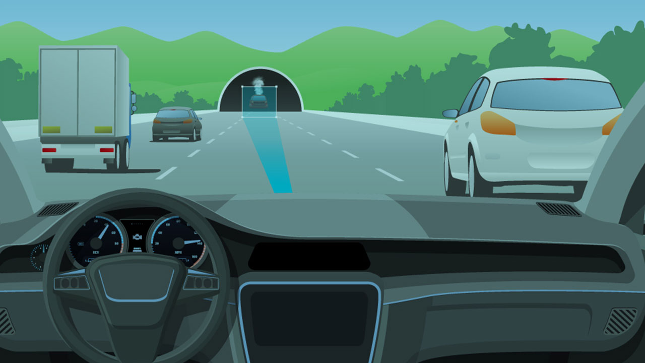
Figure 2 shows a vehicle stuck in a tunnel with smoke coming out of it. The vehicle is approximately 100 m away and the tunnel height is 3 m.
 Figure 2 The Front Radar of the
Approaching Car Needs a High-enough Angle Resolution to Differentiate between
the Tunnel and the Stopped Vehicle. mmWave Sensors Can See through Any
Visibility Conditions, like Smoke.
Figure 2 The Front Radar of the
Approaching Car Needs a High-enough Angle Resolution to Differentiate between
the Tunnel and the Stopped Vehicle. mmWave Sensors Can See through Any
Visibility Conditions, like Smoke.In order to identify the vehicle in the tunnel shown in Figure 2, the sensor needs to differentiate it from the tunnel ceiling and walls.
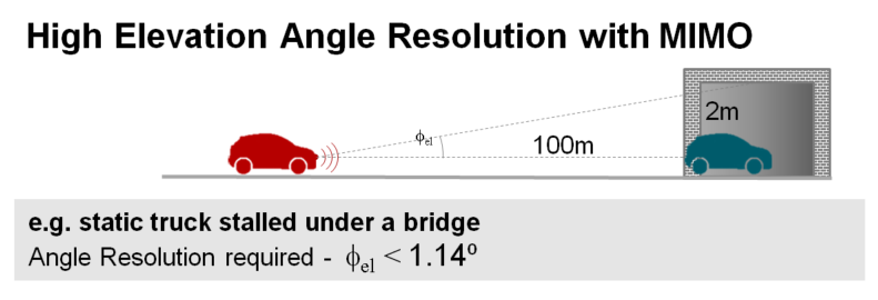
Achieving the scene classification requires these elevation and azimuth angle resolutions:
Where 2 m is the tunnel height minus the vehicle height, 100 m is the distance between the approaching vehicle with imaging radar and the vehicle stopped in the tunnel and 3.5 m is the distance between the stopped vehicle and the tunnel walls. Figure 3 illustrates how mmWave sensors enable high angular resolution in order to “see” the vehicle.
 Figure 3 How mmWave Sensors Achieve
High Elevation Angular Resolution with Multiple-input Multiple-output (MIMO)
Radar.
Figure 3 How mmWave Sensors Achieve
High Elevation Angular Resolution with Multiple-input Multiple-output (MIMO)
Radar.Relying on other optical sensors may be challenging in certain weather and visibility conditions. Smoke, fog, bad weather, and light and dark contrasts are challenging visibility conditions that can inhibit optical passive and active sensors such as cameras and LIDAR, which may potentially fail to identify a target. TI mmWave sensors, however, maintain robust performance despite challenging weather and visibility conditions.
Currently, the only sensor that keeps robustness in every weather and visibility condition, and that can achieve 1-degree angular resolution in both azimuth and elevation (and even lower with super-resolution algorithms) is the imaging radar sensor.
Conclusion
Imaging radar using TI mmWave sensors provides great flexibility to sense and classify objects in the near field at a very high resolution, while simultaneously tracking targets in the far field up to 400 m away. This high-resolution and cost-effective imaging radar system can enable level 2 and 3 ADAS applications as well as high-end level 4 and 5 autonomous vehicles, and act as the primary sensor in the vehicle.
Additional Resources
- Learn more about TI imaging radar and the AWR2243 device.
- Watch the video, “mmWave Automotive Imaging Radar System – Long Range Detection.”
- Read the blog post, “Are we there yet? Expectations vs. reality in autonomous driving.”
- Start your design with the “Automotive imaging radar reference design using the 77-GHz mmWave sensor” and the Imaging radar evaluation module.
IMPORTANT NOTICE AND DISCLAIMER
TI PROVIDES TECHNICAL AND RELIABILITY DATA (INCLUDING DATASHEETS), DESIGN RESOURCES (INCLUDING REFERENCE DESIGNS), APPLICATION OR OTHER DESIGN ADVICE, WEB TOOLS, SAFETY INFORMATION, AND OTHER RESOURCES “AS IS” AND WITH ALL FAULTS, AND DISCLAIMS ALL WARRANTIES, EXPRESS AND IMPLIED, INCLUDING WITHOUT LIMITATION ANY IMPLIED WARRANTIES OF MERCHANTABILITY, FITNESS FOR A PARTICULAR PURPOSE OR NON-INFRINGEMENT OF THIRD PARTY INTELLECTUAL PROPERTY RIGHTS.
These resources are intended for skilled developers designing with TI products. You are solely responsible for (1) selecting the appropriate TI products for your application, (2) designing, validating and testing your application, and (3) ensuring your application meets applicable standards, and any other safety, security, or other requirements. These resources are subject to change without notice. TI grants you permission to use these resources only for development of an application that uses the TI products described in the resource. Other reproduction and display of these resources is prohibited. No license is granted to any other TI intellectual property right or to any third party intellectual property right. TI disclaims responsibility for, and you will fully indemnify TI and its representatives against, any claims, damages, costs, losses, and liabilities arising out of your use of these resources.
TI’s products are provided subject to TI’s Terms of Sale (www.ti.com/legal/termsofsale.html) or other applicable terms available either on ti.com or provided in conjunction with such TI products. TI’s provision of these resources does not expand or otherwise alter TI’s applicable warranties or warranty disclaimers for TI products.
Mailing Address: Texas Instruments, Post Office Box 655303, Dallas, Texas 75265
Copyright © 2023, Texas Instruments Incorporated