SSZT465 june 2019 LM63625-Q1
Coefficient of thermal expansion (CTE) is a way of describing how an object, material or liquid changes size with temperature. It’s measured by calculating the percentage change in length of a material per degree change of temperature.
When heated, the molecules of a substance begin to vibrate and move away from each other, causing expansion; removing heat creates the opposite process. While all materials expand with temperature, they do so at different rates. This difference is fundamental in understanding mechanical designs when it comes to short- and long-term reliability.
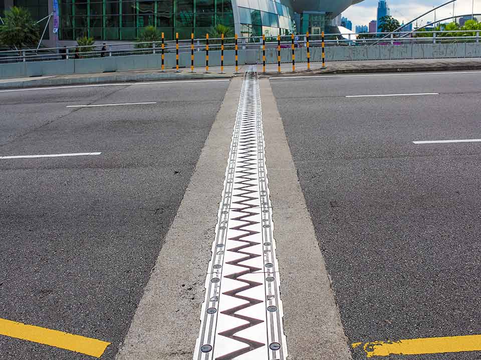
The principles of CTE apply in various industries; they are perhaps most common in construction. Figure 1 illustrates gaps in construction material that allow for expansion and reduce the pressure that various materials exert on each other.
 Figure 1 Expansion Joint on a Bridge in
Order to Prevent Cracking
Figure 1 Expansion Joint on a Bridge in
Order to Prevent CrackingCTE in Automotive Designs
It’s All in the Package
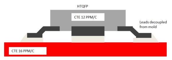
 Figure 2 Typical Leaded Package CTE vs. Typical PCB CTE
Although the footprint of a component is bigger because of the legs, often this means a larger die attached pad (DAP) is possible. A larger DAP helps manage thermals that cause expansion, also improving the thermal footprint size and amount of copper that is need to dissipate the heat generated by a power supply, for example..
When considering DC/DC converters, if you optimize the architecture of the integrated circuit to support higher-frequency operation and a better phase margin, you can reduce the number of external components to compensate for the area taken by the legs. In most cases, the package is much smaller than the inductor or capacitor when combined as a total solution size. Thus, it is possible to offer the highest levels of size reduction without compromising reliability and quality simply by designing the integrated circuit to reduce the overall bill of materials and number of external passives. An example of this is TI’s LM63625-Q1, developed specifically to minimize solution size without compromising the issues of CTE and vibration in the harsh environments of automotive systems.
With the right combination of circuit design and packaging, it is possible to manage various design challenges to create automobiles that people desire and that will remain reliable for many years.