-
Power to the Pedal: Achieving Longer-lasting 13S, 48-v Lithium-ion Battery Packs for E-bikes and E-scooters
Power to the Pedal: Achieving Longer-lasting 13S, 48-v Lithium-ion Battery Packs for E-bikes and E-scooters
Ryan Tan and Terry Sculley
The rise in popularity of electric bikes and electric scooters demands an increasing need for longer-lasting e-bike/e-scooter battery packs. A longer run time allows for farther travel and less frequent charging.
To achieve longer-lasting lithium-ion (Li-ion) batteries, you can choose one of two methods: either increase the total battery capacity or improve the energy utilization efficiency. Increasing the total battery capacity means adding more or better battery cells, which can significantly increase the overall cost of the pack. Meanwhile, improving energy utilization efficiency gives designers more usable energy without increasing capacity. There are two ways to improve energy utilization efficiency: increase the state-of-charge accuracy and/or reduce the current consumption.
| Go further with longer-lasting 13S battery packs | |

|
Find out more in our white paper, "Powering Alternative Forms of Transportation with Industrial Battery Packs." |
For a longer run time, you need to pull as much energy as possible from the battery pack; however, the battery will be permanently damaged if overdischarge occurs. In order to avoid battery overdischarge, it is critical to accurately know the battery capacity, or state-of-charge information. There are three ways to accurately measure state of charge:
- Cell voltage measurement.
- Coulomb counting.
- TI Impedance Track™ technology.
Cell voltage measurement is the easiest, but it also has low accuracy overload conditions. Coulomb counting measures and integrates current over time. But achieving better state-of-charge accuracy requires regular full-to-empty learning cycles, and state-of-charge accuracy will be affected by self-discharge and standby current. Low temperatures and an aged battery will also lower state-of-charge accuracy. Impedance Track technology directly measures the effect of discharge rate, temperature, age and other factors by learning cell impedance. Therefore, the Impedance Track method gives you better state-of-charge gauging accuracy even with an aged battery and low temperature.
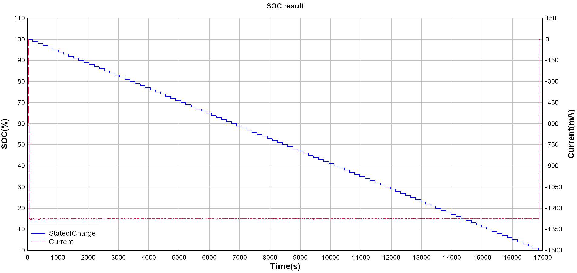
Our Accurate gauging and 50-μA standby current, 13S, 48-V Li-ion battery pack reference design uses the BQ34Z100-R2, an Impedance Track fuel gauge for Li-ion, lead-acid, nickel metal hydride and nickel cadmium batteries, and works independently of battery series-cell configurations. The design supports an external voltage translation circuit that is controlled automatically to reduce system power consumption and gives users longer run time on each charge without the concern of potential damage from overdischarge. The whole system has quite limited effects on the gauging result because of the low current consumption. As a result, I used BQStudio to read data directly from BQ34Z100-R2 under constant discharging current at room temperature. Figure 1 shows the discharge state-of-charge test result.
 Figure 1 Discharge State-of-Charge Test
Result at a Constant Discharging Current
Figure 1 Discharge State-of-Charge Test
Result at a Constant Discharging CurrentThe second method to improve energy utilization efficiency is to decrease the current consumption. To do this, it is important to consider all the electronics within the battery pack. The battery management system in the pack needs to implement additional functions beyond gauging, including monitoring the pack for the presence of potential faults, and taking appropriate action if a dangerous event is detected. These functions are realized by including an integrated battery monitor and protector, along with protection FET drive circuitry. The Accurate gauging and 50-μA standby current, 13S, 48-V Li-ion battery pack reference uses the BQ76940 together with the BQ76200 for these functions, but TI has since released a newer, integrated solution in the BQ76952, which integrates all of these functions into a single device.
The BQ76952 provides capability to measure the voltage of each cell in the pack, includes current measurement and Coulomb counting, and also supports pack temperature measurement through up to 9 thermistors. The device provides protections against adverse pack conditions, including over and under voltage protection, over current in charge and discharge, short circuit in discharge detection, and over/under temperature protection separately for charging and discharging. Whenever an adverse condition occurs, the BQ76952 first provides an alert to the MCU, then after a programmable delay will issue a fault. The device also integrates high-side NMOS protection FET drivers to control pack charging and discharging. Whenever a protection fault occurs, the device can autonomously control the protection FETs to disable charging or discharging, and can re-enable FETs when conditions allow. The device additionally provides balancing support for the pack, to prevent cells from slowly becoming unequal in voltage due to differences in leakage currents and self-discharge of the cells.
These monitoring, protection, and balancing functions do require additional pack current to operate, but the BQ76952 optimizes pack current consumption using power modes. During an active charge or discharge, the device operates at peak performance, tracking the voltage, current, and temperature continuously. But when the pack goes into an idle state, where the current drops to a low, background level, the device autonomously transitions into a sleep mode, whereby it reduces the power drawn from the pack to as low as 24uA. The BQ76952 is still detecting the pack current even in this mode, and if a charge or discharge suddenly begins, it will immediately transition back to full power operation for best performance.
While this reduces power when the pack is in the customer’s hands, the product often needs to stay on the shelf or in inventory storage for long periods of time before being purchased and put into use. To minimize the pack current and extend this shelf life, the BQ76952 also supports a shutdown mode (also referred to as ship mode), which draws 1uA, and a deepsleep mode, drawing 10uA, to give the system designer options to optimize their pack power. The device includes capability to be wakened from shutdown mode whenever a charger is attached, when a button is pressed on the unit, or the pack is plugged into a system.
The 10s-16s battery pack reference design with accurate cell measurement and high-side MOSFET control reference design provides an implementation of a battery pack that includes the BQ76952 for monitoring, protection, cell balancing, and FET drive, a BQ77216 secondary protector for redundant over/under voltage protection, an msp430 microcontroller, and a TCAN1044 CAN transceiver for communication to the rest of the system. This entire design shown below realizes a ship mode current of 10uA, and 100uA while in a standby, idle mode.

Conclusion
Overall, the Accurate gauging and 50-μA standby current, 13S, 48-V Li-ion battery pack reference design achieves accurate state-of-charge gauging (through the BQ34Z100-R2) and decreases standby and ship mode current consumption (through an optimized bias supply solution). The 10s-16s battery pack reference design with accurate cell measurement and high-side MOSFET control reference design realizes a power efficient implementation for monitoring, protection, balancing, and protection FET control to minimize current consumption and extend battery operation for the end customer. Both of these solutions work together to improve the energy utilization efficiency of e-bike battery packs, giving users longer use time.
Additional Resources
- Check out our battery management training video, “Impedance Track benefits.”