SSZT578 november 2018 LDC0851 , MSP430F67791A
In the first installment of this series, I discussed some of the limitations of mechanical tamper detection for smart meters and introduced a new inductive-based implementation using the LDC0851. In this installment, I will discuss the advantages of this implementation.
First, the solid-state switching of the LDC0851 eliminates the mechanical failures of the mechanical push-button implementation. In addition, since the LDC0851 compares the inductance of both a sense inductor and a reference inductor, it is robust against environmental effects such as humidity. The inherent matching of printed circuit board (PCB) inductors and using a single capacitor for both measurements helps achieve immunity from environmental effects. In other words, if the environment affects the sense inductor, then it should affect the reference inductor similarly, essentially subtracting out the environmental effect when comparing the reference and sense inductances.
This form of tamper detection is also immune to magnetic tampering by DC magnets. The LDC0851 can only be affected by AC magnetic fields that are precisely near the system’s sensor frequency, which is system-dependent (in the megahertz range). Generating the proper magnetic field at this precise sensor frequency is difficult. Theoretically, even if you could generate this magnetic field, it would not paralyze the system such that the output would not change to indicate a tampering occurrence. Providing the necessary AC magnetic field only causes the LDC0851’s output to constantly switch between states, which would alert the microcontroller of potential tampering.
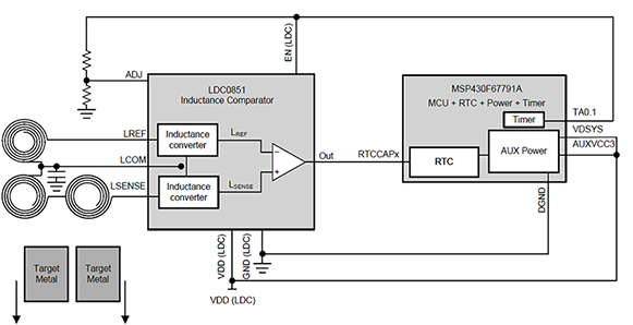
Another advantage of an inductive-based implementation is that it is possible to sense across two points with only one integrated circuit (IC) on the case by placing inductors in series. For example, you can implement the opening of both a terminal block cover and a separate main cover for an e-meter by using one sense coil-plus-metal combination to detect the terminal block cover, and a separate sense coil-plus-metal combination to detect the removal of the main cover with these two coils in series, where the series combination of the coils connects to the LDC0851.
Alternatively, to maximize the sensing range across the perimeter of the case, you can place two different coil-plus-metal combinations on opposite corners of the case. If there is an opening at one of the sense coil locations, the corresponding sense coil’s inductance would increase, causing the total sense series inductance to increase. If the increase in total inductance is sufficiently large with respect to the total reference inductance, then the LDC0851’s output would switch, indicating tampering.
To match the reference inductance with the sense inductance for this poly-coil implementation, there are two options. The first option is to duplicate the same sense-coil combination and use it for the reference coil – which is the simplest method but requires more PCB area. For this option, the number of reference coils equals the number of sense coils. The advantage is that it enables easy matching of the sense and reference coils, since you’re using the same exact coils for both scenarios.
The second option is to only have one referenced coil and design it precisely so that it produces the same approximate inductance as the total series inductance. This second option saves board space, since you’re only using one reference coil instead of using the same number of coils as for the sense coil.
For gas meters, the inductive-based implementation should be low power, since these meters are primarily powered from batteries. Low power can also be a priority for e-meters, since their auxiliary power source can be battery-powered when mains power is not available.
To reduce the average current consumption for this implementation, a microcontroller could duty-cycle the enable pin of the LDC0851 so that the device is only enabled for the minimum time necessary to get a valid reading. In the Case Tamper Detection Reference Design Using Inductive Sensing, the MSP430F67791A is the microcontroller that duty-cycles the LDC0851 to obtain an average current consumption of approximately 2µA.
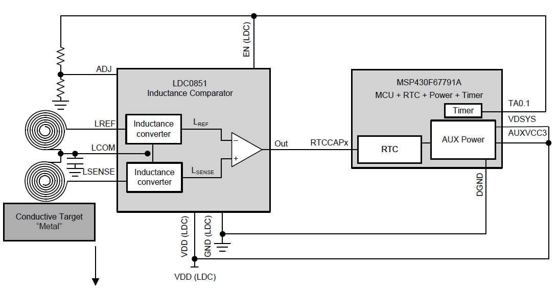
Figure 1 and Figure 2 are block diagrams illustrating the two variants of the reference design. Figure 1 shows the one-sense-coil variant to detect the opening of an e-meter’s terminal block cover. For this variant, the sense and reference coils are placed next to each other, which is a valid configuration for boards with two layers or more. For boards with four layers, an additional option is to stack the reference coils and sense coils on top of each other as mentioned in LDC0851 Stacked Coil Design Considerations. Figure 2 shows the two-sense-coil variant, which uses two sense coils in series to detect the opening of both the e-meter’s terminal block cover and main cover.
 Figure 1 One-sense-coil Variant Block Diagram
 Figure 2 Two-sense-coil Variant Block Diagram
In the reference design, the LDC0851 is used specifically for detecting the opening of an e-meter case; however, the same mechanism is applicable for detecting gas meter case tampering. In addition to providing the pulses on the LDC0851’s enable pin, the MSP430F67791A microcontroller in this design has an internal real-time-clock with capture pins to log the time of case tampering. The MSP430F67791A also provides the power source for the LDC0851, with support for backup power sources. Mains power could power the LDC0851 when it is available and automatically switch to a backup power source when it is not available.
Using the reference design, you could design a case tamper detection implementation based on the specifications of the e-meter or gas meter case dimensions.
Additional Resources
- View all TI smart e-meter reference designs.
- Watch the TI training series, “Anti-Tamper Techniques to Thwart Attacks on Smart Meters.”