-
How to Power Next-generation ADAS Camera Modules SSZT628 september 2018 TPS54388C-Q1 , TPS57112C-Q1 , TPS57114C-Q1 , TPS62423-Q1 , TPS62424-Q1
-
How to Power Next-generation ADAS Camera Modules
How to Power Next-generation ADAS Camera Modules
David Snook
Updated August 2019
We’ve all heard the headlines lately about efforts going into developing and testing a new generation of autonomous vehicles. Developing advanced driver assistance systems (ADAS) is an important trend in the automotive industry to make driving safer and pave the way to autonomous driving. This push toward increased driver assistance and automation relies on a variety of different sensors designed into the cars of tomorrow, such as cameras, radar or LIDAR.
Camera modules, in particular, will provide critical data for the autonomous decision-making process, such as reading road signs; thus, the requirements on car vision systems are rapidly evolving to gather more information. For example, the pixel count of CMOS image sensors used in cameras is increasing, which leads to more data processing and higher power consumption. Another constraint is that the camera modules must be small, efficient and discreet – no one wants to ruin the design of a car with a camera sticking out from the bodywork. So how can you power your next-generation ADAS camera modules to support more data-gathering capability and smaller sizes?
You first have to think about whether to use a DC/DC switching regulator or a low-dropout regulator (LDO) for each of the rails in your system. LDOs are a great choice if your current requirements are low or if the rail is very sensitive to noise (such as the analog input rail of a CMOS image sensor). However, with the trend toward higher pixel counts and increased power consumption, a DC/DC switching regulator will often be a better choice to minimize power losses and temperature rise.
Then, you must decide on your power tree. You have three main options:
- Fully integrated: using a dedicated power-management integrated circuit (PMIC) to provide all of the camera modules’ power rails. This simplifies the solution but lacks flexibility.
- Fully discrete: using a discrete power supply to generate each power rail. This gives you maximum flexibility but can require more design time to choose all of the different ICs and sometimes has a larger total solution size compared to a higher integrated solution.
- Partial integration: using a mix of single- and multichannel power supplies to simplify the design, with more flexibility than using only a PMIC.
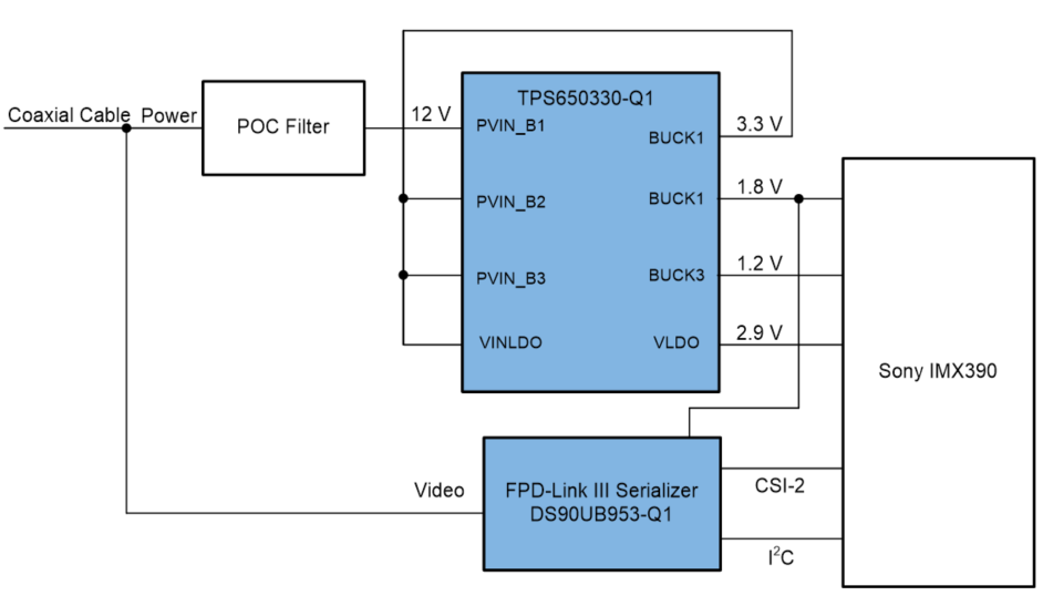
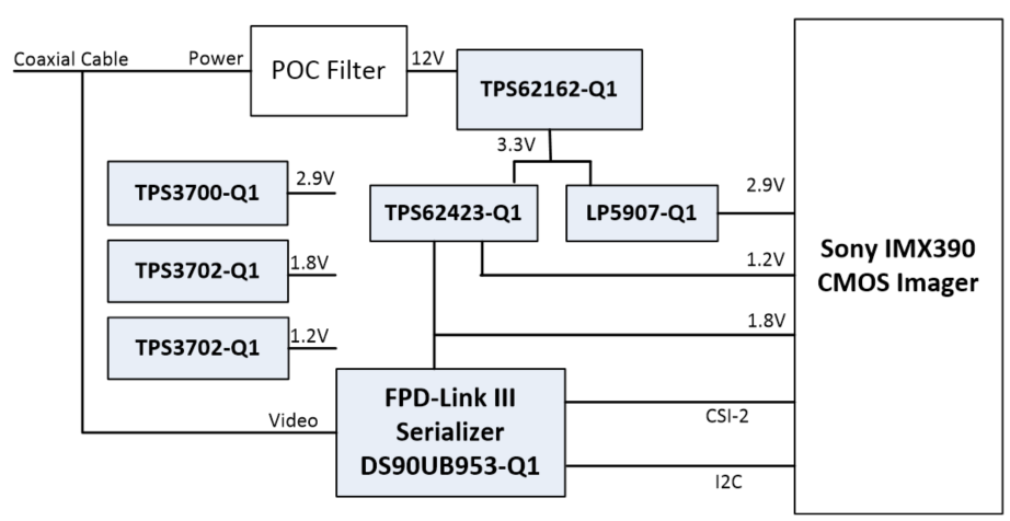
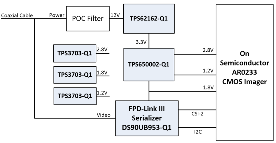
We offer solutions for all of these options, as you can see in Figure 1-Figure 3.
 Figure 1 Example of the Highly
Integrated Approach with the Automotive
Camera PMIC Power Supply Reference Design with Power Over Coax
Filter
 Figure 2 Example of the Discrete
Approach with the Automotive 2-MP camera module reference design
with MIPI CSI-2 video interface, FPD-Link III and
POC
 Figure 3 Example of the Partial
Integration Approach with Added Precision Diagnostics for the Supply Voltage
Rails
Figure 3 Example of the Partial
Integration Approach with Added Precision Diagnostics for the Supply Voltage
RailsUsing a dual step-down DC/DC converter for partial integration provides a simpler bill of materials than a discrete DC/DC switching regulator and offers more flexibility on the layout than a full-fledged PMIC, which is a good compromise between making your design simpler and keeping the layout flexible to best address the size constraints of camera modules.
TI is releasing two new fixed-output-voltage versions of a dual-channel step-down converter that are good choices for your automotive camera module designs. The TPS62423-Q1 and TPS62424-Q1 have a small 3mm-by-3mm package and no need for external resistor dividers.
The fixed output voltages of these new devices were chosen specifically to meet the power requirements of the latest CMOS image sensors, as you can see in Table 1.
| Image sensor | Rail 1 | Rail 2 | Power |
|---|---|---|---|
| OX01B40 | 1.8V | 1.1V | TPS62424-Q1 |
| OV2311, OX03A10, OV7916, AR0231AT | 1.8V | 1.2V | TPS62423-Q1 |
| OV2775 | 1.8V | 1.3V | TPS62424-Q1 |
| OV10640, OX02A10, OV10642, OV10650, OV7261 | 1.8V | 1.5V | TPS62423-Q1 |
It’s an exciting time to be an engineer working on automotive electronics and ADAS, and TI is working hard to support you with the products you need to get your next camera module power-supply design rolling, no matter which power architecture you decide on.
Additional Resources
- Take a look at TI’s ADAS portal.
- Try our interactive block diagram for ADAS camera modules to find products and reference designs.
- Get some tips on reducing ripple for sensitive and dynamic rails in the blog post, “Ripple reduction techniques for sensitive and dynamic rails in automotive camera modules.”
IMPORTANT NOTICE AND DISCLAIMER
TI PROVIDES TECHNICAL AND RELIABILITY DATA (INCLUDING DATASHEETS), DESIGN RESOURCES (INCLUDING REFERENCE DESIGNS), APPLICATION OR OTHER DESIGN ADVICE, WEB TOOLS, SAFETY INFORMATION, AND OTHER RESOURCES “AS IS” AND WITH ALL FAULTS, AND DISCLAIMS ALL WARRANTIES, EXPRESS AND IMPLIED, INCLUDING WITHOUT LIMITATION ANY IMPLIED WARRANTIES OF MERCHANTABILITY, FITNESS FOR A PARTICULAR PURPOSE OR NON-INFRINGEMENT OF THIRD PARTY INTELLECTUAL PROPERTY RIGHTS.
These resources are intended for skilled developers designing with TI products. You are solely responsible for (1) selecting the appropriate TI products for your application, (2) designing, validating and testing your application, and (3) ensuring your application meets applicable standards, and any other safety, security, or other requirements. These resources are subject to change without notice. TI grants you permission to use these resources only for development of an application that uses the TI products described in the resource. Other reproduction and display of these resources is prohibited. No license is granted to any other TI intellectual property right or to any third party intellectual property right. TI disclaims responsibility for, and you will fully indemnify TI and its representatives against, any claims, damages, costs, losses, and liabilities arising out of your use of these resources.
TI’s products are provided subject to TI’s Terms of Sale (www.ti.com/legal/termsofsale.html) or other applicable terms available either on ti.com or provided in conjunction with such TI products. TI’s provision of these resources does not expand or otherwise alter TI’s applicable warranties or warranty disclaimers for TI products.
Mailing Address: Texas Instruments, Post Office Box 655303, Dallas, Texas 75265
Copyright © 2023, Texas Instruments Incorporated