SSZT654 august 2018
Low-dropout regulators (LDOs) provide power in all types of applications. But for an LDO to operate normally, you need an output capacitor. A common issue when designing LDOs into an application is selecting the correct output capacitor. In this post, I will explore different considerations when selecting an output capacitor and how it may affect your LDO.
What Are Capacitors?
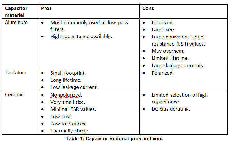
A capacitor is a device used to store electric charge consisting of one or more pairs of conductors separated by an insulator. Capacitors are most commonly made of aluminum, tantalum or ceramic. Each of these materials has their own pros and cons when used in a system, as listed in Table 1. I generally recommend ceramic capacitors because of their minimal variation in capacitance, as well as their low cost.
What’s Capacitance?
While a capacitor is a device that stores electric charge, capacitance is the ability to store electric charge. In an ideal world, the value written on a capacitor would be exactly the same as the amount of capacitance it provides. But we don’t live in an ideal world, and so you cannot take capacitors at face value. You’ll see later that the capacitance of a capacitor may be as little as 10% of its rated value. This might be caused by derating from being biased with a DC voltage, derating from changes in temperature or manufacturer tolerances.
DC Voltage Derating
Given the dynamic nature of capacitors (storing and dissipating electric charge in a nonlinear fashion), some polarization may occur without the application of an external electric field; this is known as “spontaneous polarization.” Spontaneous polarization results from the material’s inert electric field, which gives the capacitor its initial capacitance. Applying an external DC voltage to the capacitor creates an electric field that reverses the initial polarization and then “locks” or polarizes the rest of the active dipoles into place. The polarization is tied to the direction of the electric field within the dielectric.
As shown in Figure 1, the locked dipoles do not react to AC voltage transients; as a result, the effective capacitance becomes lower than it was before applying the DC voltage.
 Figure 1 DC Voltage Derating
Figure 2 shows the effects of applying voltages to a capacitor and the resulting capacitance. Notice how the larger case size loses less capacitance; this is because larger case sizes have more dielectric between the conductors, which reduces the strength of the electric field and locks on fewer dipoles.
 Figure 2 Capacitance vs. DC Bias vs. Capacitor Size
Temperature Derating
Like all electronics, capacitors have a temperature rating over which their performance is specified. This temperature derating can commonly be found underneath the numerical value of the capacitor. Table 1 is a temperature coefficient rating decoder table for capacitors.
| First character: low temperature | Second character: high temperature | Third character: maximum change over temperature | |||
|---|---|---|---|---|---|
| Character | Temperature (°C) | Character | Temperature (°C) | Character | Change (%) |
| Z | 10 | 2 | 45 | A | ±1.0 |
| Y | -30 | 4 | 65 | B | ±1.5 |
| X | -55 | 5 | 85 | C | ±2.2 |
| 6 | 105 | D | ±3.3 | ||
| 7 | 125 | E | ±4.7 | ||
| 8 | 150 | F | ±7.5 | ||
| 9 | 200 | P | ±10 | ||
| R | ±15 | ||||
| S | ±22 | ||||
| T | +22, -33 | ||||
| U | +22, -56 | ||||
| V | +22, -82 | ||||
The majority of LDO junction temperatures are usually specified from -40°C to 125°C. Based on this temperature range, X5R or X7R capacitors are best.
As shown in Figure 3, temperature alone affects capacitance much less than the DC bias derating, which may reduce capacitance values by as much as 90%.
 Figure 3 Capacitance vs. Temperature vs. Temperature Coefficient
Manufacturer Tolerances
Due to the nonideal characteristics of real capacitors, the capacitance value itself may change based on the material and size of the capacitor. Companies that manufacture capacitors and other passive electronic components will have a general standard for what values of capacitance their components can tolerate. In this post, I’ll use ±20% as the manufacturing tolerance when calculating capacitance.
A Real Application
A common LDO application would be to take an input voltage from a 3.6V battery and drop it to power a microcontroller (1.8V). In this example, I’ll use a 10µF X7R ceramic capacitor in a 0603 package. The 0603 package refers to the dimensions of the capacitor: 0.06 inches by 0.03 inches.
Let’s find the true capacitance value of this capacitor for this application:
- DC bias derating: By using the chart provided by the manufacturer of the DC bias characteristics for a capacitor (Figure 2), you can see that the capacitance value will be 7µF.
- Thermal derating: If this capacitor were to be in an ambient temperature of 125°C, you would see another 15% drop in capacitance value, bringing the new total to 5.5µF.
- Manufacturer tolerance: Taking into account the manufacturer tolerance of ±20%, the final value for the capacitance will be 3.5µF.
As you can see, a 10µF capacitor has a true value of 3.5µF when put into these conditions. The capacitance value has degraded to about 65% of the nominal value. Obviously not all of these conditions would apply, but it is important to know the range of capacitance values that a capacitor can provide for your application.
Conclusion
Although LDOs and capacitors seem simple at first, there are other factors at play that determine the effective capacitance needed for normal operation of an LDO.
Additional Resources
- Learn more LDO basics in the LDO basics blog post series.
- For more information about thermals, read my blog post, “LDO basics: Thermals – How hot is your application?”
- Check out the Low Dropout Regulators Quick Reference Guide.