-
Fast Current Loop Performance: Better than We Thought, and Measurable in Your Own Lab
Fast Current Loop Performance: Better than We Thought, and Measurable in Your Own Lab
Brian Fortman
Jun 19, 2018
In June 2017, I posted about unprecedented current-loop performance from an off-the-shelf microcontroller (MCU) achieved by the C2000™ family with the fast current loop (FCL) software solution. Closing the current loop in less than 1ms had previously been the domain of custom application-specific integrated circuit (ASIC) and field-programmable gate arrays (FPGAs) with parallel data-path architectures.
The DesignDRIVE C2000 FCL release at that time was targeted for the industrial drive development kit (IDDK) and, while you could measure the loop time with a scope, analyzing the control bandwidth of the current loop meant using an expensive dynamometer and control response analyzer tools in your own laboratory environment.
In early 2018, TI released its second version of the FCL solution, with these updates:
- Improved loop control bandwidth.
- Free software frequency response analysis (SFRA) tools.
- New low-cost evaluation tools – including the dynamometer.
- Simultaneous FCL control of two motors (dual axis) example on a single C28x central processing unit (CPU).
Better Bandwidth
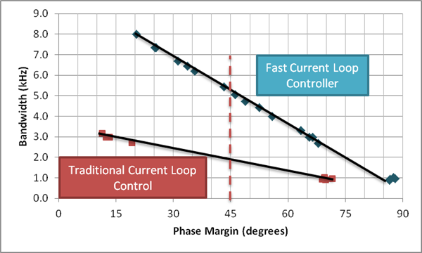
The most important update to share is the fact that our own in-depth measurements exceeded our previous expectations of “over 3kHz” of control bandwidth versus traditional approaches. Figure 1 summarizes the results of FCL tests versus traditional current-loop designs. In each case, we designed control loops for a target bandwidth and measured the phase margin. By plotting these results against each other, you can see the dramatic difference in bandwidth at a given phase margin between the two control approaches.
Every one of these tests uses only a 10kHz pulse-width modulation (PWM) carrier frequency and in-line current sensing enabled by INA240 sensors on the low-voltage three-phase gallium nitride (GaN) inverter BoosterPack. Using in-line sensing enables the current to be sampled twice per PWM period during the polarity transition points. The results shown in both curves of Figure 1 leverage the double sampling technique. (For reference, an incremental or ABZ encoder provides the shaft angle feedback.)
Most in the industry measure their current-loop bandwidth at 45 degrees of phase margin in order to avoid instability situations. If you compare the results in Figure 1 at 45 degrees (the dashed red line), you will see that the FCL controller delivers about 5kHz of control bandwidth, while the traditional approach is less than 2kHz.
 Figure 1 Gain Margin vs. Phase Margin Results Comparing FCL to Traditional Current-loop Control
For more details on how we obtained this plot, see the technical brief, “Performance Analysis of Fast Current Loop (FCL) in Servo Drives Using SFRA on C2000™ Platform.” Or better yet, see the Additional Resources section at the end of this post and validate these measurements for yourself.
SFRA Tools, Now with Motor-control Support
So how will you measure the frequency and phase margin of FCL or the specific controllers that you design in the future? One option is to leverage the free C2000 SFRA tool. Part of the powerSUITE tool chain, the SFRA tool enables the measurement of the open loop gain and plant frequency response of a closed-loop digital controller using only software. Taking advantage of software libraries linked into the C2000 project and executed in silicon as well as the digital debugging connection, you take the measurements and plot them in the SFRA PC application. This makes the in-system measurement of digital control loop bandwidth, gain margin and phase margin quick and easy.
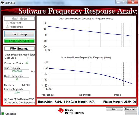
Now available for motor current control analysis as well, these tools are included for free in the FCL download. Figure 2 shows an example of the frequency response plots of an FCL project as presented by the SFRA tool.
 Figure 2 SFRA PC Graphical User Interface
But I Need a Motor and a Controlled Load to Measure the Response
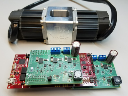
That’s true, and a dynamometer machine and the hardware tools you need to control it can be really expensive. But not in this case! You can replicate our performance analysis with a bundled package that includes a C2000 Delfino™ controller, two GaN three-phase inverters and dual motor dynamometer in a single orderable product on the TI store. See Figure 3.
 Figure 3 A Low-cost GaN-based Bundle for Motor-control Performance Testing
Available for less than $600, this is the same configuration that produced the test results shown in Figure 2. The inverter BoosterPack development boards included in this bundle also include the in-phase current sensing, and therefore enable double sampling of the current per PWM period.
If you are interested in a quick way to see FCL results on your own bench and establish your own performance motor-control development and testing environment, this bundle can get you moving fast. It also serves as a great tool for testing your motor-control ideas beyond FCL – for speed and position loop control, for example.
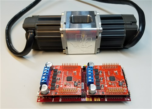
We have also tested FCL with TI’s DRV8305N three-phase motor drive BoosterPack evaluation module with integrated sense amplifiers. In this case, the current is sampled on the inverter shunts; therefore, a single sample is taken per PWM period. These tools have also been packaged with the two-motor dynamometer and are shown in Figure 4.
 Figure 4 A Low-cost, Shunt-based Sensing Bundle for Motor-control Performance Testing
Dual-axis Support
Another development with the FCL release is that the software project incorporates the control of two motors concurrently from a single C28x core. We decided to use a second FCL instance in order to incorporate the load-side control. The coordination of analog-to-digital converter (ADC) sampling, field-oriented control (FOC) processing and PWM updates are resolved in this release. We used the second controller to act as the load, but in your dual-axis servo drive architecture, you can use these axes independently for whatever your industrial application may require. When you investigate this for yourself, you will see that both loops are capable of delivering the same bandwidth results as in Figure 1.
Additional Resources
- Download the latest FCL project controlSUITE Software projects and design files.
- Check out the FCL GaN dyno bundle, the DRV dyno bundle or just the dynamometer.
- Download the “Fast Current Loop (C28x) Library User’s Guide.”
- Download the application report, “Dual Motor Control Using FCL and Performance Analysis Using SFRA on TMS320F28379D LaunchPad.”
- Find resources and reference designs for motor drives here.
- To learn more about TI’s FCL solutions for C2000 MCUs, check out:
IMPORTANT NOTICE AND DISCLAIMER
TI PROVIDES TECHNICAL AND RELIABILITY DATA (INCLUDING DATASHEETS), DESIGN RESOURCES (INCLUDING REFERENCE DESIGNS), APPLICATION OR OTHER DESIGN ADVICE, WEB TOOLS, SAFETY INFORMATION, AND OTHER RESOURCES “AS IS” AND WITH ALL FAULTS, AND DISCLAIMS ALL WARRANTIES, EXPRESS AND IMPLIED, INCLUDING WITHOUT LIMITATION ANY IMPLIED WARRANTIES OF MERCHANTABILITY, FITNESS FOR A PARTICULAR PURPOSE OR NON-INFRINGEMENT OF THIRD PARTY INTELLECTUAL PROPERTY RIGHTS.
These resources are intended for skilled developers designing with TI products. You are solely responsible for (1) selecting the appropriate TI products for your application, (2) designing, validating and testing your application, and (3) ensuring your application meets applicable standards, and any other safety, security, or other requirements. These resources are subject to change without notice. TI grants you permission to use these resources only for development of an application that uses the TI products described in the resource. Other reproduction and display of these resources is prohibited. No license is granted to any other TI intellectual property right or to any third party intellectual property right. TI disclaims responsibility for, and you will fully indemnify TI and its representatives against, any claims, damages, costs, losses, and liabilities arising out of your use of these resources.
TI’s products are provided subject to TI’s Terms of Sale (www.ti.com/legal/termsofsale.html) or other applicable terms available either on ti.com or provided in conjunction with such TI products. TI’s provision of these resources does not expand or otherwise alter TI’s applicable warranties or warranty disclaimers for TI products.
Mailing Address: Texas Instruments, Post Office Box 655303, Dallas, Texas 75265
Copyright © 2024, Texas Instruments Incorporated