SSZT744 april 2018 TMS320F280049
I recently shared with you the production announcement of TI’s new Piccolo™ F28004x microcontroller (MCU) series, which has been optimized for power control applications.
Key features of Piccolo F28004x for high-performance power control include:
- On-chip windowed comparators.
- A programmable digital-to-analog converter with slope compensation.
- High-resolution pulse-width modulation (PWM) one-shot and global reload features to simplify variable frequency-interleaved power-converter implementations.
- Programmable PWM blanking.
- A high-resolution PWM deadband.
- Tight coupling between on-chip comparators and PWM timer modules.
- Multiple, independent, high-speed, high-resolution analog-to-digital converters.
- A high-performance floating-point central processing unit with an optional parallel control law accelerator.
Two reference designs – the Interleaved CCM Totem Pole Bridgeless Power Factor Correction (PFC) Reference Design and the Highly Efficient, 1.6kW High Density GaN-Based 1MHz CRM Totem-Pole PFC Converter Reference Design – demonstrate the benefits of these features in actual systems. The designs are totem-pole power factor correction (PFC) converter references, ideal for power-supply applications used in telecom, server and network, industrial, and electric vehicle (EV) onboard charging (OBC).
The references are similar in voltage level (AC input, 400VDC output) and efficiency (+98.7%) and use similar components (600V gate drivers and gallium nitride [GaN] power stage) and features (soft starting, adaptive dead-time, phase shedding) – but there are some key differences in the implementation.
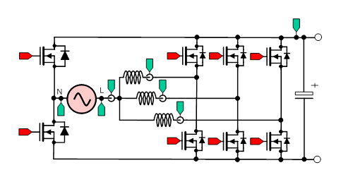
The interleaved continuous conduction mode (CCM) reference design demonstrates a three-phase interleaved topology (Figure 1) switching at 100kHz PWM with CCM operation. This technique is typically used for applications ~5kW and above that require high efficiency at a moderate power density. The switching frequency is limited to about 200kHz due to switching losses.
 Figure 1 PFC Topology for Interleaved
Continuous Conduction Mode (CCM) Reference Design
Figure 1 PFC Topology for Interleaved
Continuous Conduction Mode (CCM) Reference DesignThe totem-pole PFC converter reference design demonstrates a two-phase interleaved topology (Figure 2) switching at a maximum frequency of 1.2MHz PWM with critical conduction mode (CRM) operation. CRM mode avoids the switching losses and enables sustained high efficiency at even higher PWM frequencies compared to CCM operation. Because of the high frequency, the design can be smaller and denser while maintaining high efficiency.
 Figure 2 PFC Topology for Totem-pole
PFC Converter Reference Design
Figure 2 PFC Topology for Totem-pole
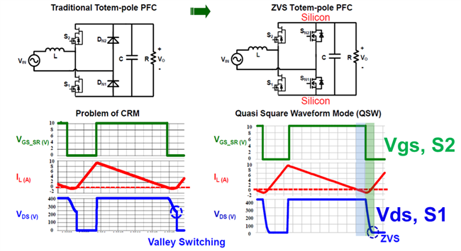
PFC Converter Reference DesignThe main challenge is to achieve zero voltage switching (ZVS) across line and load conditions over the full AC cycle. This becomes difficult as the input voltage increases above half the DC bus voltage value, where you can only get valley switching without any extra current fed into the inductor. With valley switching and not complete ZVS operation, metal-oxide semiconductor field-effect transistor (MOSFET) switching losses will increase significantly as the switching frequency increases.
The solution for extending ZVS operation over the entire AC cycle is to extend the conduction time of the synchronous switch so that there is a negative current in the inductor, which will allow the drain-to-source voltage to swing to zero. The challenge and solution is described in Figure 3. The theory is straightforward, but the implementation is quite challenging across the full load and operation range and relies on the capabilities of Piccolo F28004x real-time controllers.
 Figure 3 CRM vs. CRC (ZVS)
Techniques
Figure 3 CRM vs. CRC (ZVS)
TechniquesThe Highly Efficient, 1.6kW High Density GaN-Based 1MHz CRM Totem-Pole PFC Converter Reference Design is truly a cutting edge, with an implementation and efficiency capability beyond what is currently on the market from power supply customers. To help you develop similar products, we are also providing a set of software tools to adapt the solution. The DigitalPower Software Development Kit (SDK) for C2000™ MCUs supports both reference designs.
This SDK is a cohesive set of software infrastructure, tools and documentation designed to minimize C2000 MCU-based digital power system development time. The software includes firmware that runs on C2000 digital power evaluation modules (EVMs) and reference designs in the TI Designs library and is a repository for all digital power applications.
Included in the DigitalPower SDK is powerSUITE, a package of digital power-supply software design tools that includes these components:
- Solution Adapter: Customize code examples to run on example or custom hardware using the same topology as a TI solution.
- Compensation Designer: Design digital compensators to achieve your desired closed-loop performance.
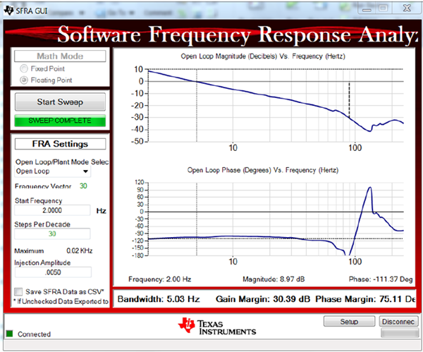
- Software Frequency Response Analyzer (SFRA): Plot and measure the open-loop gain (loop gain Bode plot) and plant (power stage) frequency response to assess and optimize the stability and robustness of your digital power-supply control loop, as seen in Figure 4.
 Figure 4 PowerSUITE SFRA Tool
Showing the PFC Voltage-loop Response of the Interleaved CCM Reference
Design
Figure 4 PowerSUITE SFRA Tool
Showing the PFC Voltage-loop Response of the Interleaved CCM Reference
DesignI’m sure that if as a power-supply designer, you’re ready to get started. Have fun, good luck and be on the lookout for more TI reference designs for cutting-edge power control.