How to Minimize Time to Market in Your USB Type-C™ and USB Power Delivery Designs

Many electronic system designers are interested in implementing USB Type-C™ and USB Power Delivery (PD) while getting their products to market as quickly as possible. Most USB Type-C applications require a microcontroller (MCU) because of the need for firmware configuration via the I2C, Serial Peripheral Interface (SPI) and/or Universal Asynchronous Receiver Transmitter (UART) data communication protocols.
But what if you could implement USB Type-C and USB PD without any firmware configuration or an external MCU and get your product to market fast?
Let’s say that you are designing an AC/DC power adaptor with the UCC28740 flyback controller using opto-coupled feedback and the TPS25740B USB Type-C and USB PD source controller, as shown in Figure 1.
 Figure 1 AC/DC Adapter Simplified
Schematic Using USB Type-C and USB PD
Figure 1 AC/DC Adapter Simplified
Schematic Using USB Type-C and USB PDThe TPS25740B has three control pins (CTL1, CTL2, and CTL3) which adjust the output voltage of the power supply based on the voltage requested by the attached sink. In other words, the CTL pins adjust the resistive feedback network of the optocoupler transmitting to the UCC28740 in order to output the desired voltages on the VBUS line in real time. This is what enables effortless USB Type-C PD adoption without the need for any firmware implementation.
Table 1 below shows the TPS25740B CTL pin states as a function of the target voltage on VBUS.

|
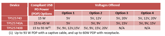
The voltages that are advertised depend on the USB PD source controller and how the device is configured. There are a variety of USB PD source controllers on the market today that can be configured to advertise a range of commonly desired voltages. One family of these devices and their voltage offerings can be seen below in Table 2.
|
In conclusion, there are a variety of USB Type-C and PD source controllers available today that can be used to reduce time to market. So, consider using a device without the need for firmware or an MCU for your USB Type-C and PD design and get your product to market fast.
Additional Resources
- Start your design with these reference designs
IMPORTANT NOTICE AND DISCLAIMER
TI PROVIDES TECHNICAL AND RELIABILITY DATA (INCLUDING DATASHEETS), DESIGN RESOURCES (INCLUDING REFERENCE DESIGNS), APPLICATION OR OTHER DESIGN ADVICE, WEB TOOLS, SAFETY INFORMATION, AND OTHER RESOURCES “AS IS” AND WITH ALL FAULTS, AND DISCLAIMS ALL WARRANTIES, EXPRESS AND IMPLIED, INCLUDING WITHOUT LIMITATION ANY IMPLIED WARRANTIES OF MERCHANTABILITY, FITNESS FOR A PARTICULAR PURPOSE OR NON-INFRINGEMENT OF THIRD PARTY INTELLECTUAL PROPERTY RIGHTS.
These resources are intended for skilled developers designing with TI products. You are solely responsible for (1) selecting the appropriate TI products for your application, (2) designing, validating and testing your application, and (3) ensuring your application meets applicable standards, and any other safety, security, or other requirements. These resources are subject to change without notice. TI grants you permission to use these resources only for development of an application that uses the TI products described in the resource. Other reproduction and display of these resources is prohibited. No license is granted to any other TI intellectual property right or to any third party intellectual property right. TI disclaims responsibility for, and you will fully indemnify TI and its representatives against, any claims, damages, costs, losses, and liabilities arising out of your use of these resources.
TI’s products are provided subject to TI’s Terms of Sale (www.ti.com/legal/termsofsale.html) or other applicable terms available either on ti.com or provided in conjunction with such TI products. TI’s provision of these resources does not expand or otherwise alter TI’s applicable warranties or warranty disclaimers for TI products.
Mailing Address: Texas Instruments, Post Office Box 655303, Dallas, Texas 75265
Copyright © 2023, Texas Instruments Incorporated