-
How to Maintain Automotive Front Camera Thermal Performance on a Hot Summer Day
How to Maintain Automotive Front Camera Thermal Performance on a Hot Summer Day
Today, when people begin researching the purchase of a car, they’re likely to read about advanced driver assistance systems (ADAS) that offer features to increase both convenience and safety. A few examples of ADAS capabilities are lane departure warning, pedestrian detection, automatic emergency braking, adaptive cruise control and road sign recognition.
One theme common to all of these capabilities is that they’re all hazards that drivers need to avoid or events that require drivers to take action based on objects on or near the road. Cars equipped with front camera modules sense the road ahead and provide vehicles with object-detection capabilities. Additionally, cars equipped with radar provide precise distance measurements, but the focus of this blog post will be on the front cameras.
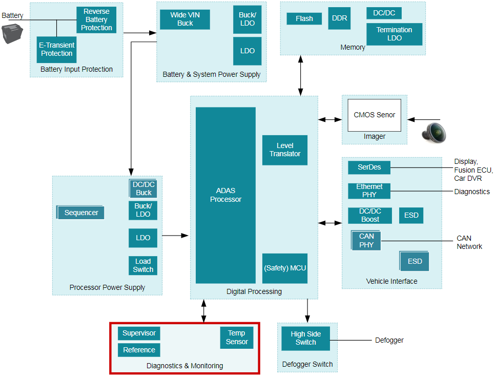
There is some variation with front camera modules depending on the desired ADAS feature set offered for a particular vehicle, but Figure 1 shows the common components of an automotive front camera.
 Figure 1 System Block Diagram for a
Mono Front Camera
Figure 1 System Block Diagram for a
Mono Front CameraFigure 1 is an example of a front camera with an integrated processing unit that leverages controller area network (CAN) as the primary communication interface. In a surround-view distributed camera system, the processors are removed from the individual camera modules and a centralized electronic control unit (ECU) handles the processing. In this distributed camera system, each camera would communicate with the ECU over a flat panel display (FPD)-Link III interface. The front camera module is often mounted between the rearview mirror and the windshield so that it gets a clear view of the road ahead. However, this placement behind the windshield exposes the front camera module to direct sunlight, which raises the board temperature of the front camera.
Front camera modules have heaters to remove the condensation that can build up on the windshield and distort the camera’s view. The temperature of the heater and heater driver requires monitoring to ensure that it remains within operating conditions. Finally, the power-management integrated circuit (PMIC) and JacintoTM TDAx ADAS processor will dissipate heat and contribute to an elevated front camera board temperature.
The complementary metal-oxide semiconductor (CMOS) image sensor operates up to 125°C, but the image quality will begin to degrade before reaching that operating temperature. That is because of increased current/noise within the CMOS image sensor as the temperature increases. A temperature-degraded image sensor can negatively impact the functionality of the critical vision-based safety systems I previously discussed.
Additionally, exceeding the 105°C ambient temperature limit for many FPD-Link serializers can compromise communication in a surround-view distributed camera system. Often the PMIC, CMOS image sensor, FPD-Link SerDes and ADAS processors will have some form of internal die temperature sensor. However, these internal temperature sensors are very inaccurate when attempting to approximate board temperature, while external temperature sensors are required for an effective board-level thermal-management strategy.
For front camera modules with on-board ADAS processing capabilities, such as that provided by Jacinto TDAx processors, the TMP112-Q1 is a digital temperature sensor IC that can monitor the board temperature with ±1°C accuracy between -40°C and +125°C. The TMP112-Q1 can communicate directly with the ADAS processor over the I²C interface, which gives the front camera full autonomy for thermal management and protects the critical ADAS processor. For surround-view/distributed cameras, the LMT87-Q1 is a cost-effective option that will monitor the board temperature with ±2.7°C accuracy between -40°C and +150°C. You can connect the analog output of the LMT87-Q1 to the dual function GPIO/analog-to-digital converter (ADC) pins of the FPD-Link SerDes, and the temperature data would transmit to a central ADAS ECU.
Vision-based ADAS safety systems are helping shape the future of the automotive industry while increasing driver, passenger and pedestrian safety. The front camera is a vital component to ensure the safe operation of vision-based systems. Over-temperature conditions caused by heat sources like direct sunlight and the on-chip heater risk damaging the front camera board. TI offers several easy-to-use solutions to addresses these concerns and help you implement a complete thermal-management strategy.
Additional Resources
- Check out TI’s temperature sensor portfolio.
- Visit the learning center to learn more about designing with temperature sensors.
- Learn more about front camera architectures.
- Learn more about TI’s ADAS solutions.