-
Back to the Basics: What Is HART Protocol and How Does It Work?
Back to the Basics: What Is HART Protocol and How Does It Work?
Gavin Bakshi
Communications in industrial automation systems enable the transfer of data, commands and other information to streamline process control and factory automation. It would be unrealistic for an engineer to monitor every piece of equipment in the factory (and that certainly would decrease productivity).
One way to monitor field equipment automatically is through 4-20 mA loop sensor transmitters. The primary variable (PV) is communicated as a current level between 4 mA and 20 mA on a two-wire loop-powered system. One downfall of this method is that you can only monitor one variable at a time, so the Highway Addressable Remote Transducer (HART) protocol enables the transfer of more information on the same two-wire system. The HART protocol has been a common method for communication in industrial automation for many years. In this post, I’ll look at what HART is and how it works. But first, let’s look at how the method originated.
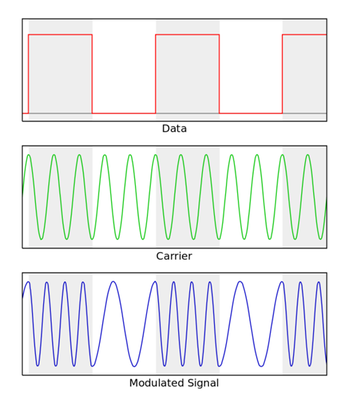
In the late 1990s, the telecom industry adopted the Bell 202 standard to transmit caller ID information on the same line as voice signals. Audio frequency-shift keying (FSK), which uses modulated tones to produce a digital signal, transfers the digital information containing the phone number. The data transfers at a rate of 1,200 bps using 1,200 Hz and 2,200 Hz frequencies representing a binary 1 or 0, respectively, as shown in Figure 1.
 Figure 1 Frequency-shift Keying
Modulation
Figure 1 Frequency-shift Keying
ModulationThe caller ID information does not interfere with the voice signal so that all of the information can transfer over the same physical wiring. The inclusion of the Bell 202 FSK allowed the transceiver to send large amounts of data before the receiver handset was lifted and was then filtered and used to communicate caller ID information. Once the handset was lifted the FSK signal would terminate and the modulated signal carrying the voice information would then be demodulated and transmitted to the receiver ear-piece.
In the caller ID example, the voice signal represents the PV. Similarly, in industrial applications, the signal that must be monitored at all times is known as the primary measured value. The primary measured value could be the temperature or pressure level measured in the field.
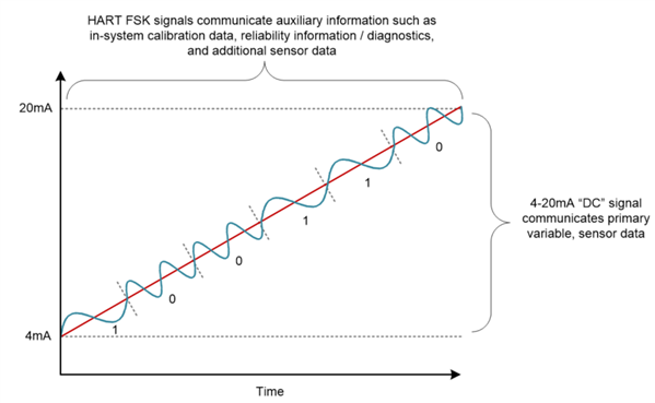
The HART modem modulates and demodulates the signal using FSK, just like the Bell 202 system. Digital information such as sensor or device identification information, calibration data, or other diagnostics, can now be transferred over the same two-wire loop as the 4-20mA signal. This system is typically referred to as a “hybrid” system, as it combines both digital and analog signals. Figure 2 shows the coupled digital and analog signal.
 Figure 2 4-20mA and HART
Information
Figure 2 4-20mA and HART
InformationHART has two main operational modes: point-to-point and multi-drop mode. In point-to-point mode, there is a single master and a single slave. The benefit of this mode is that the digital data easily transfers over the existing 4-20mA line, enabling more detailed device monitoring even with existing infrastructure. In multi-drop mode, there are multiple masters and slaves; only HART FSK data can be transmitted and the current is fixed at 4mA. Multi-drop mode is beneficial if many field devices are communicating with a single control system, but the loop current cannot be used to constantly monitor a variable.
HART is a versatile method of communication for a variety of industrial automation applications. The method itself offers many benefits that reduce cost, simplify designs and provide results, including:
- Transmission of digital information without interrupting the primary analog signal.
- Simple implementation by using the existing 4-20mA two-wire infrastructure.
- Flexible operations to meet the needs of varying systems.
The DAC8740H family integrates the HART modem along with all supporting components, such as a reference and oscillator, for easy implementation into your system. If you are interested in learning more about 2-wire systems, see the 2-Wire 4-20mA Sensor Transmitters blog post series on the E2E™ Community.
Additional Resources
- Download the DAC8740H datasheet.
- View the DAC8740H product folder.
- Check out the Highly-Accurate, Loop-Powered, 4mA to 20mA Field Transmitter with HART® Modem Reference Design.
This technical article was co-authored by Audrey Dearien.