-
Powering a 12V Bus with 24V Batteries in Automotive Applications
Powering a 12V Bus with 24V Batteries in Automotive Applications
George Lakkas
24V systems are common in commercial trucks, including heavy-duty pickup trucks, as well as military vehicles that require extra power.
Converting power from 24V batteries to 12V for low-voltage electronics inside a vehicle cockpit necessitates the use of a DC/DC converter with a wide input-voltage range, fast load transient response and complete system protection, as shown in Figure 1.
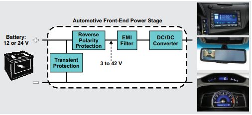 Figure 1 24V Automotive Battery
System
Figure 1 24V Automotive Battery
System24V systems (just like 12V systems) can experience wide input-voltage variations as a result of cold-crank and load-dump events, as shown in Figure 2. These peak load-dump transients can be as high as 60V.
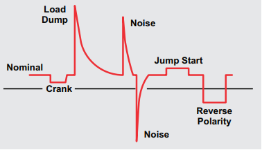 Figure 2 24V Battery Input-voltage
Transient Events
Figure 2 24V Battery Input-voltage
Transient EventsA 24V-to-12V buck DC/DC converter has to be able to handle a wide input-voltage variation (up to 60V), provide tight load regulation and system protection, and have strong drivers to enable high conversion efficiency with external metal-oxide semiconductor field-effect transistors (MOSFETs).
The 280W Automotive Dual-Phase Synchronous Buck Reference Design with 24VDC Input, 12VDC Output showcases a 24V-to-12V automotive battery power-conversion design. The resulting 12V output of the converter is available for various electronics inside the cockpit.
The synchronous buck reference design uses the LM5119-Q1 automotive-qualified two-phase pulse-width modulation (PWM) buck controller and is designed to downconvert 24V to 12V at 20A for a total of 240W of output power. This 240W design is 120mm by 70mm and includes all of the components required for the power supply (Figure 3).
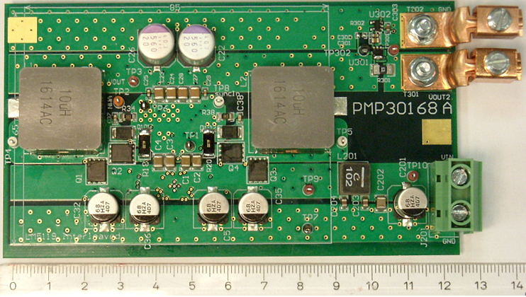 Figure 3 Synchronous Buck Reference
Design 24V to 12V Buck Converter for Automotive Batteries
Figure 3 Synchronous Buck Reference
Design 24V to 12V Buck Converter for Automotive BatteriesThe reference design will support cranking down to 18V and load-dump transients (input voltage overshoot) to 58V.
Efficiency is >97% from 6A to 20A with a power loss less than 9W, as shown in Figure 4.
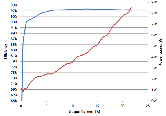 Figure 4 Synchronous Buck Reference
Design 24V-to-12V Buck Converter Efficiency and Power Loss
Figure 4 Synchronous Buck Reference
Design 24V-to-12V Buck Converter Efficiency and Power LossAs shown in Figure 5, the load regulation has only 2mV of deviation over the load current range.
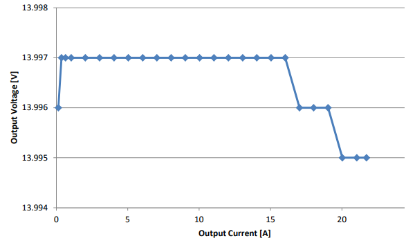 Figure 5 Synchronous Buck Reference
Design Load Regulation
Figure 5 Synchronous Buck Reference
Design Load RegulationOutput ripple voltage is less than 10mVpp, with noise at 20mVpp (Figure 6).
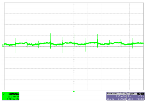 Figure 6 Synchronous Buck Reference
Design Output Voltage Ripple
Figure 6 Synchronous Buck Reference
Design Output Voltage RippleIf you are designing an automotive battery 24V-to-12V buck DC/DC converter, consider this reference design for your toolkit. It comes with all of the technical documents and files to enable a quick implementation so that you and your customers can start steering the wheel.
Additional Resources:
- Read the Analog Applications Journal article, “Designing the front-end DC/DC conversion stage to withstand automotive transients.”
- Check out the automotive applications portal.
IMPORTANT NOTICE AND DISCLAIMER
TI PROVIDES TECHNICAL AND RELIABILITY DATA (INCLUDING DATASHEETS), DESIGN RESOURCES (INCLUDING REFERENCE DESIGNS), APPLICATION OR OTHER DESIGN ADVICE, WEB TOOLS, SAFETY INFORMATION, AND OTHER RESOURCES “AS IS” AND WITH ALL FAULTS, AND DISCLAIMS ALL WARRANTIES, EXPRESS AND IMPLIED, INCLUDING WITHOUT LIMITATION ANY IMPLIED WARRANTIES OF MERCHANTABILITY, FITNESS FOR A PARTICULAR PURPOSE OR NON-INFRINGEMENT OF THIRD PARTY INTELLECTUAL PROPERTY RIGHTS.
These resources are intended for skilled developers designing with TI products. You are solely responsible for (1) selecting the appropriate TI products for your application, (2) designing, validating and testing your application, and (3) ensuring your application meets applicable standards, and any other safety, security, or other requirements. These resources are subject to change without notice. TI grants you permission to use these resources only for development of an application that uses the TI products described in the resource. Other reproduction and display of these resources is prohibited. No license is granted to any other TI intellectual property right or to any third party intellectual property right. TI disclaims responsibility for, and you will fully indemnify TI and its representatives against, any claims, damages, costs, losses, and liabilities arising out of your use of these resources.
TI’s products are provided subject to TI’s Terms of Sale (www.ti.com/legal/termsofsale.html) or other applicable terms available either on ti.com or provided in conjunction with such TI products. TI’s provision of these resources does not expand or otherwise alter TI’s applicable warranties or warranty disclaimers for TI products.
Mailing Address: Texas Instruments, Post Office Box 655303, Dallas, Texas 75265
Copyright © 2023, Texas Instruments Incorporated