SSZT840 december 2017
In the sixth (and most recent) installment of this series, I started the discussion about actuation by highlighting the importance of the delayed trip feature in implementing deadband delays in peak current-mode control with zero software overhead. In this installment, I will explore pulse-width modulation (PWM) valley switching, which is a soft switching technique geared toward scavenging several central processing unit (CPU) cycles, while also improving system efficiency and performance.
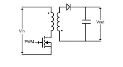
In order to understand the cycle scavenging made possible through the valley-switching technique, it is imperative to first learn about the feature itself. Take a look at the flyback converter shown in Figure 1.
 Figure 1 Flyback Converter
A flyback converter is a simple switch-mode power supply that generates a DC output from either an AC or DC input. In this post, I’ll limit the discussion to the operation of a flyback in discontinuous conduction mode. For operation in this particular mode, the power stage is designed in such a way as to allow the transformer to completely demagnetize during each switching cycle. At the start of the switching period, when the PWM turns on, the primary-side current ramps up from zero. At this stage, energy from the source transfers to the transformer. When enough energy is stored in the transformer, the PWM turns off; current flows to the secondary windings and the stored energy in the transformer is delivered to the load.
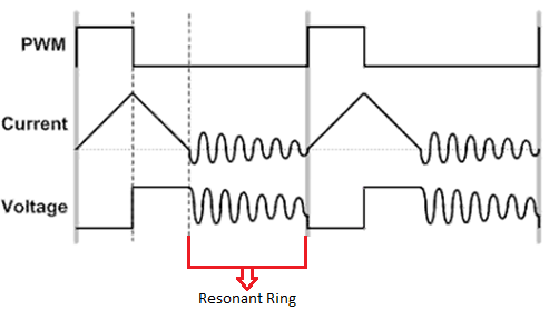
Note that the current in the secondary ramps down to zero, completely demagnetizing the transformer during every switching cycle. After the demagnetizing time, there is a delay before the primary-side switch turns on again to start the next switching cycle. This delay during which neither the diode nor the metal-oxide semiconductor field-effect transistor (MOSFET) are conducting is known as dead time or resonant time. During dead time, the interaction between the primary inductance of the transformer and the parasitic capacitance at the switch node generates a resonant ring. This is clearly illustrated in the flyback waveforms shown in Figure 2.
 Figure 2 Flyback Converter
Valley-switching Waveforms for Low Loads
Figure 2 Flyback Converter
Valley-switching Waveforms for Low LoadsValley switching is a soft switching technique that minimizes switching losses by turning on the PWM for the next switching cycle at a point when the current through the switch is at its minimum. This happens when the resonant rings during dead time for the voltage across the switch are at their valley point. For some applications, it might be best to turn on the PWM at the first valley point, while for others it might be better to wait until the valley point of the third or fourth resonant ring for improved efficiency. Note that resonant oscillations are highly dependent on circuit parasitics and operating conditions, which make it very difficult to detect this optimal valley point.
While this technique traditionally used external valley-switching submodules, that has not been the most ideal solution from a real-time control perspective due to the complex software algorithms required to detect valley points of the resonant rings. The other downside to this approach is the fact that that the submodules can usually only detect the first valley point accurately. This is a major limiting factor for applications where switching at a later valley point instead of the first significantly improves switching efficiency. Adding an external submodule for valley switching also increases bill of materials costs and adds complexity to the overall system, making this approach unfeasible.
C2000™ microcontrollers (MCUs) integrate the valley-switching submodule to provide an on-chip solution that addresses the challenges I’ve mentioned without compromising real-time performance. Enhancements made to type 4 PWM modules allow the latest C2000 MCUs to keep track of the number of resonant rings elapsed so that they can switch the PWM at the optimal valley point instead of limiting themselves to the first valley. This significantly improves efficiency and minimizes switching losses compared to external submodules that can only detect the first valley point.
Moreover, C2000 MCUs scavenge a considerable number of cycles from the main processors by implementing valley switching in hardware with minimal CPU intervention. This gives C2000 MCUs a clear advantage over other general-purpose MCUs that rely heavily on cycle-intensive software algorithms to perform valley switching, burning several CPU cycles in the process.
As you can see, C2000 MCUs bring tremendous value to customers compared to the competition. First, the ability to detect multiple valley points offers a more efficient solution. Second, implementing valley switching in hardware scavenges a significant number of cycles from the main processors, thereby minimizing latencies and improving real-time performance of the system. Third, by integrating the valley switching submodule on-chip, C2000 MCUs also provide significant cost savings and reduce overall system complexity.
Moving on from valley switching, in the next installment I will look at simultaneous writes to PWM registers, as well as one-shot and global reload, that have great potential to scavenge CPU cycles at the actuation stage, enabling C2000 MCUs to improve real-time performance.
Additional Resources
- Read the Applied Power Electronics Conference and Exposition (APEC) 2017 paper, “Digital Controller with Integrated Valley Switching Control for Light Load Efficiency and THD Improvements in PFC Converter.”
-
Download the technical reference manuals for TMS320F2837xD Dual-Core Delfino™ microcontrollers and TMS320F28004x Piccolo™ microcontrollers.